
Tube-in-tube energy-saving lamp
An energy-saving lamp and tube-in-tube technology, which is applied in energy-saving control technology, electric lamp circuit layout, cooling/heating device of lighting devices, etc. It is easy to burn out light-emitting diodes and other problems, so as to improve the heat dissipation effect, increase the luminous efficiency, and reduce the secondary energy consumption.
Patent Information
- Authority / Receiving Office
- CN · China
- Patent Type
- Applications(China)
- Current Assignee / Owner
- Publication Date
- 2014-04-02
- Estimated Expiration
- Not applicable · inactive patent
Smart Images
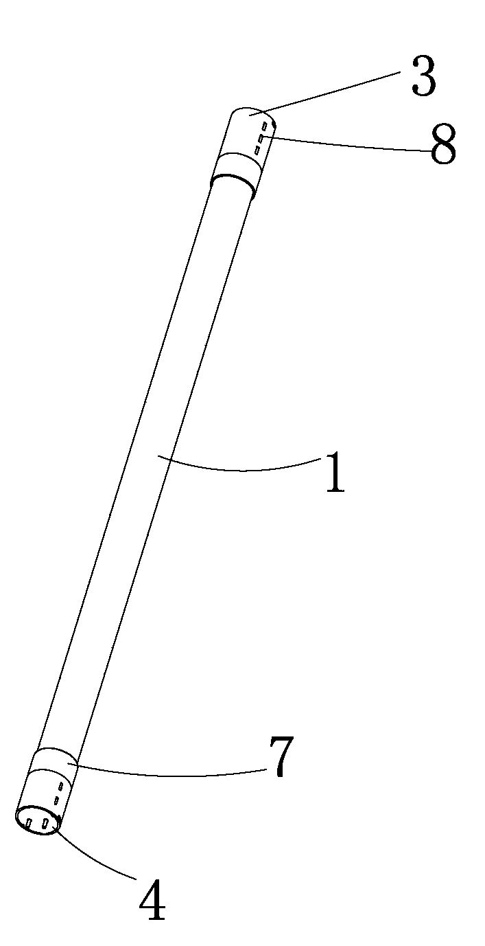
Figure 1 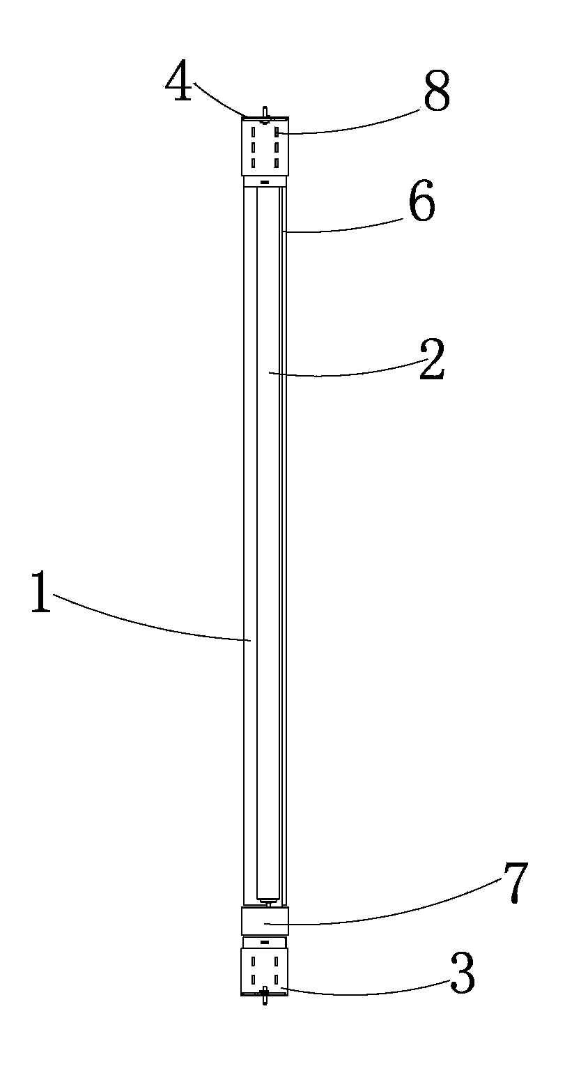
Figure 2 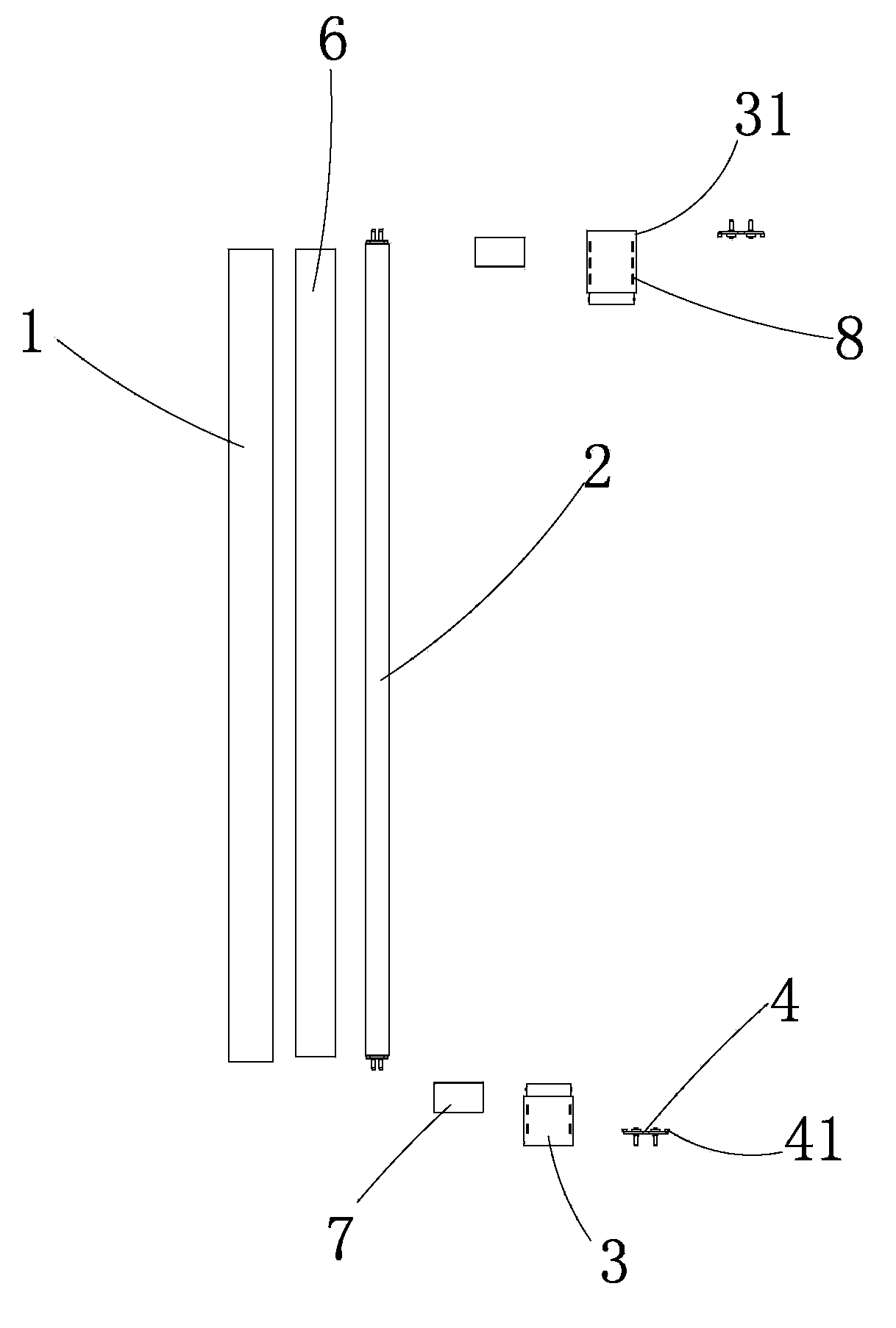
Figure 3
Abstract
Description
technical field
[0001] The invention belongs to the technical field of energy-saving lamps, in particular to a tube-in-tube energy-saving lamp. Background technique
[0002] Energy-saving lamps are lamps that use high-brightness white light-emitting diodes as light sources. They have many advantages such as high luminous efficiency, low power consumption, long life, easy control, maintenance-free, safety and environmental protection, etc. It is a new generation of solid cold light source, light color Soft, bright, colorful, low loss, low energy consumption, suitable for long-term lighting in various public places such as homes, shopping malls, banks, hospitals, hotels and restaurants.
[0003] Among them, the tube-in-tube energy-saving lamp is a new type of energy-saving product converted from T8 to T5. Using it to replace the traditional inductive T8 fluorescent lamp can save 50-70% of lighting power; and using it to replace the T5 fluorescent lamp can save 40-60% of elect...
Examples
Embodiment Construction
[0029] The present invention will be described in further detail below in conjunction with the specific embodiments and the accompanying drawings, but the embodiments of the present invention are not limited thereto.
[0030] Such as Figure 1 to Figure 4 As shown, a tube-in-tube energy-saving lamp provided by the present invention includes a transparent glass sleeve 1, a three-primary color light-emitting tube 2, ferrules 3 arranged at both ends of the transparent glass sleeve 1 and guide posts arranged at one end of the ferrule 3 4. A rectifier 5 is arranged in the ferrule 3, a plug 7 is arranged between the transparent glass sleeve 1 and the ferrule 3, and the cross-section of the reflective sheet 6 is in the shape of a semicircle arc, and the three primary color light-emitting tubes 2 are arranged on the transparent Inside the glass casing 1, and the three primary color light-emitting tubes 2 are installed on the side of the plug 7 close to the reflective sheet 6 (that is,...