

An electromagnetic switching valve
An electromagnetic switching valve and valve body technology, which is applied to the valve details, valve device, valve housing structure, etc., can solve the problems of weak coordination stability of the control valve body 2, complex riveting process, and low riveting efficiency, so as to avoid positioning Unstable offset, reduced production cost, and improved production efficiency
Patent Information
- Authority / Receiving Office
- CN · China
- Patent Type
- Patents(China)
- Current Assignee / Owner
- Publication Date
- 2016-01-20
Smart Images
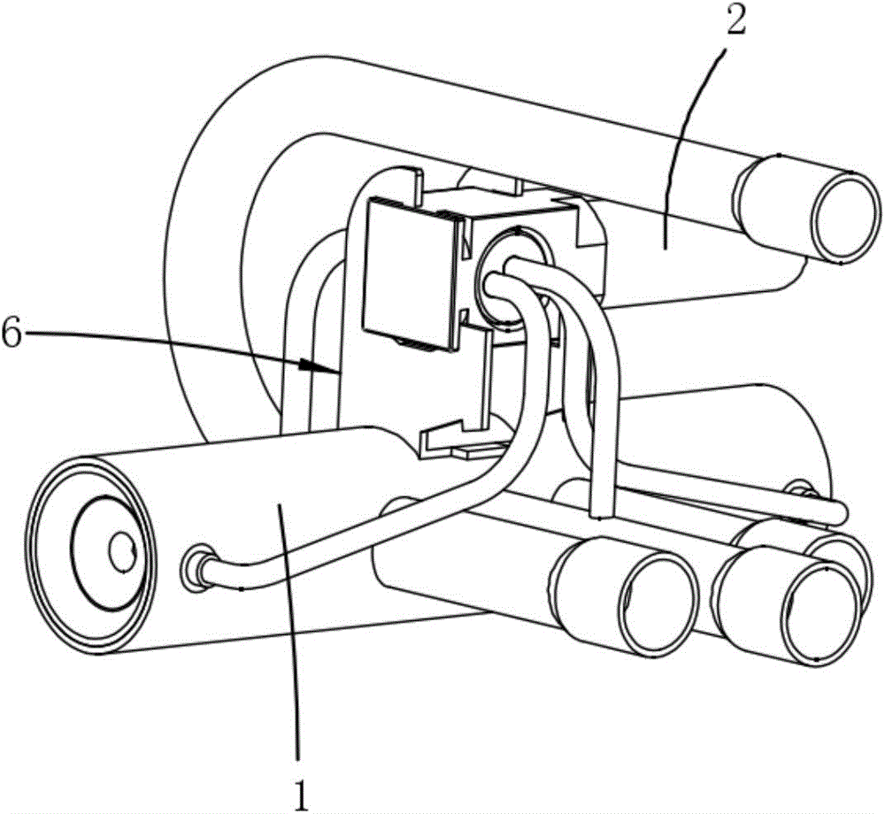
Figure 1 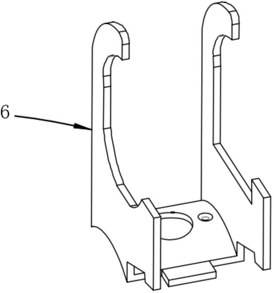
Figure 2 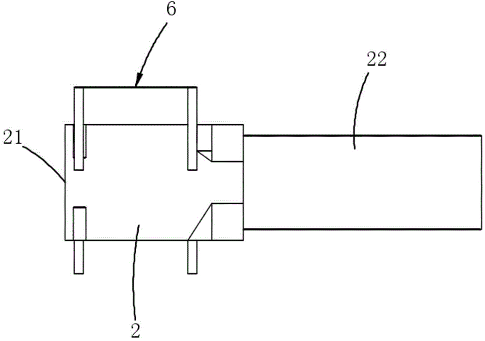
Figure 3
Abstract
Description
Technical field:
[0001] The invention relates to the technical field of electromagnetic switching valves used in the air-conditioning and refrigeration industry, in particular to an electromagnetic switching valve. Background technique
[0002] Electromagnetic switching valve is an important part of heat pump air conditioner, suitable for central and split air conditioners, etc. The action of the existing electromagnetic switching valve is to use the high and low pressure difference in the system, and use the switching of the electromagnetic coil of the control valve to switch the flow path of the main valve body 1, and then realize the change of the refrigerant flow direction in the system. The control valve is connected with the main valve body 1 through a fixing bracket 6 . The existing fixing frame 6 is riveted at both ends, which has technical problems such as large riveting deformation and complicated riveting process, and the cooperation stability with the control va...
Examples
Embodiment 1
[0023] Example 1, see Figure 4 to Figure 6 Shown: an electromagnetic switching valve, including a main valve body 1, a control valve body 2 and a fixed frame 6 punched and formed by an integral die. The connecting bracket 4, the second side are provided with a round hole fixing frame 5, the buckle type fixing frame 3 and the round hole fixing frame 5 stand upright on both sides of the connecting bracket 4 respectively, the buckle type fixing frame 3, the connecting bracket 4 and the round hole The fixing frame 5 is connected into one body, the connecting bracket 4 is fixed on the main valve body 1, the side of the control valve valve body 2 close to the valve body end 21 is pierced through the round hole fixing frame 5, and the other side of the connecting conduit 22 is fixed on the Buckle mount 3.
[0024] The buckle-type fixing frame 3 includes a first sheet, the lower end of which is connected to the connecting bracket 4, and a buckle with one side opening is punched out ...