

Aero-engine rotor stack-assembling method and device
An aero-engine and assembly method technology, applied in the direction of engine components, machines/engines, safety devices, etc., can solve problems such as low coaxiality, achieve the effects of reducing noise pollution, saving installation time and costs, and improving stability
Patent Information
- Authority / Receiving Office
- CN · China
- Patent Type
- Applications(China)
- Current Assignee / Owner
- Publication Date
- 2014-07-02
- Estimated Expiration
- Not applicable · inactive patent
Smart Images
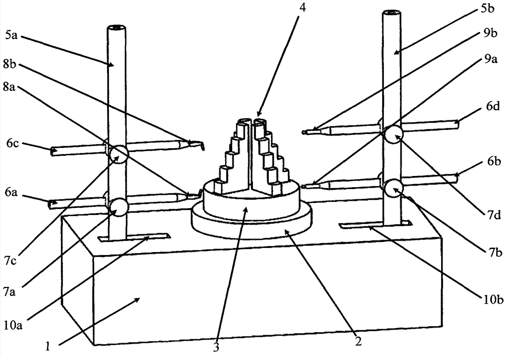
Figure 1 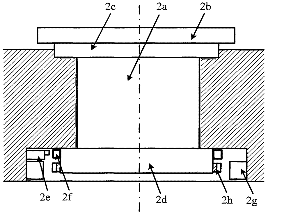
Figure 2
Abstract
Description
technical field
[0001] The invention belongs to mechanical assembly technology, and mainly relates to an aeroengine rotor stacking assembly method and device. Background technique
[0002] Aeroengine assembly is the last link in the manufacturing process of aeroengine, and it is also one of the most important manufacturing links. Under the conditions of the existing aero-engine design scheme and processing technology level, the quality of assembly and work efficiency have an important impact on the quality, performance and production efficiency of the engine. Therefore, in the assembly process, the coaxiality of the installed rotor should be improved as much as possible, so as to reduce the vibration of the aero-engine and improve the performance of the aero-engine. However, in actual production, the assembly of aero-engines is completely manual assembly. The level of assembly accuracy and stability depends entirely on the experience and technical level of the assemblers. T...
Examples
Embodiment Construction
[0020] Below in conjunction with accompanying drawing, the present invention is described in further detail:
[0021] A method and device for stacking and assembling aero-engine rotors. The method and device are as follows: a four-jaw hydraulic chuck 4 is arranged at the center of a centering and tilting workbench 3 . The left moving guide rail 10a and the right moving guide rail 10b are symmetrically distributed on the base 1 on both sides of the air bearing shaft system 2, the left column 5a is installed on the left moving guide rail 10a, and the right column 5b is installed on the right moving guide rail 10b. On the left column 5a, the left upper column connector 7c and the left lower column connector 7a are movably adjusted sequentially from top to bottom, and the left upper horizontal measuring rod 6c is horizontally nested on the left upper column connector 7c. The sensor 8b is fixedly connected with the upper left lateral measuring rod 6c; the lower left lateral measuri...