
Swing press for forging
A stamping machine and forging technology, which is applied in the field of new forging stamping machines, can solve the problem of large stamping load and achieve the effect of eliminating position deviation
Patent Information
- Authority / Receiving Office
- CN · China
- Patent Type
- Patents(China)
- Current Assignee / Owner
- Publication Date
- 2017-04-12
Smart Images
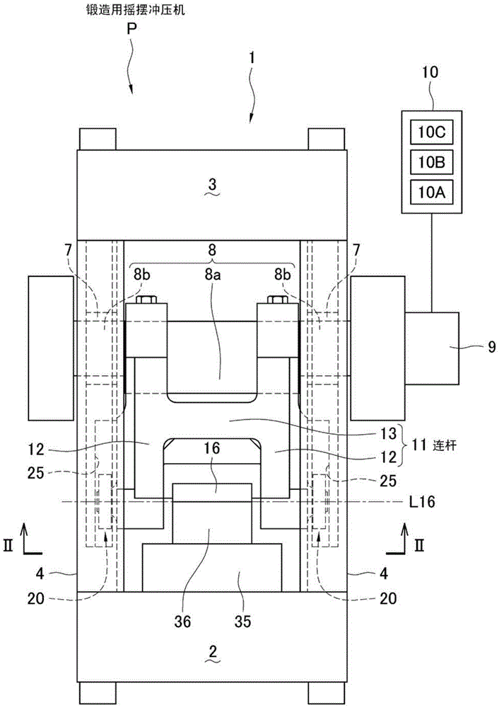
Figure 1 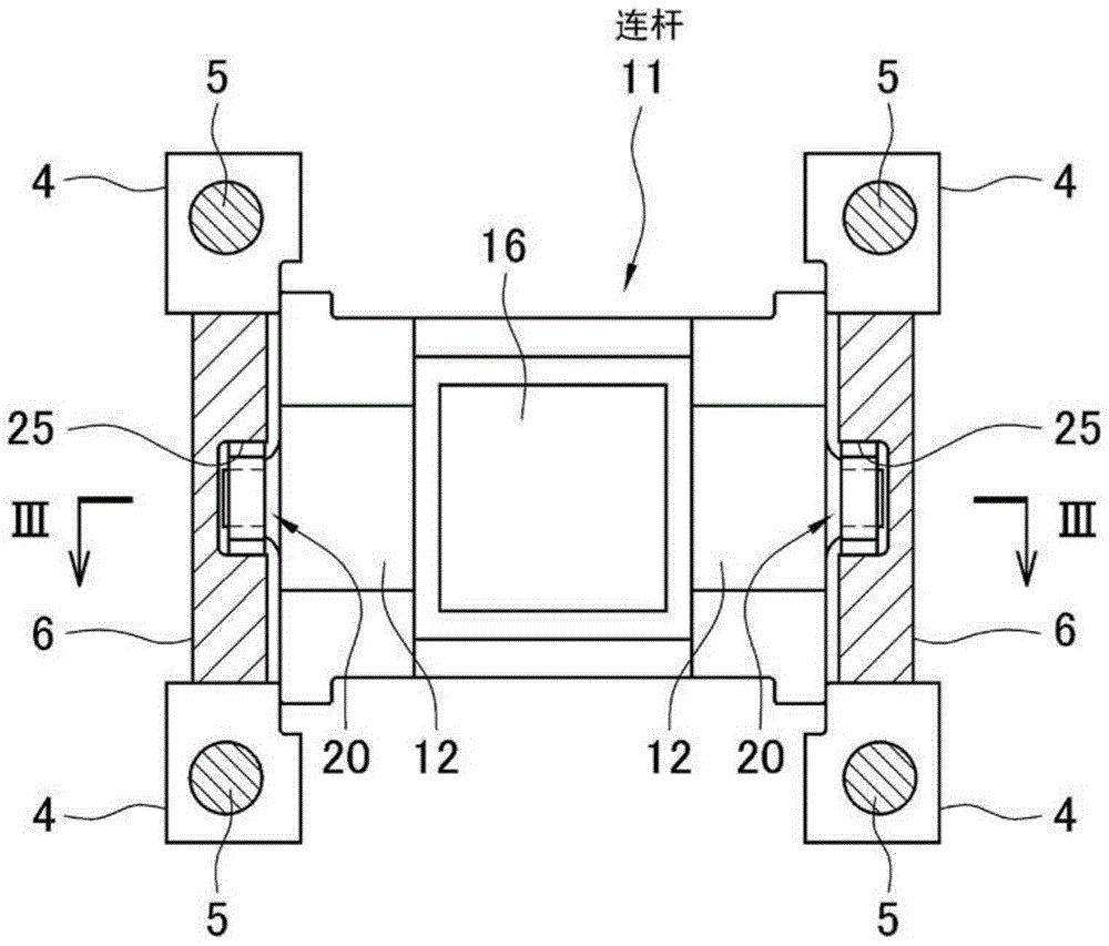
Figure 2 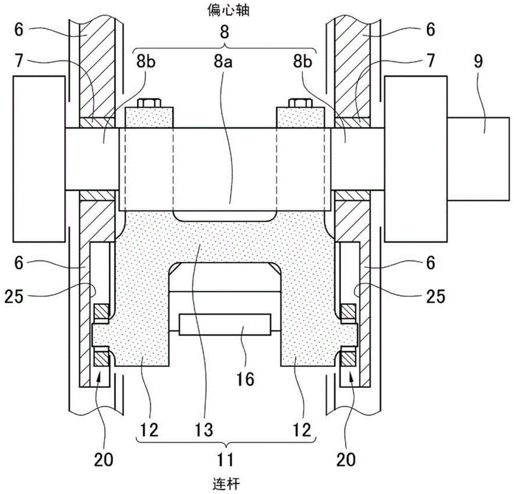
Figure 3
Abstract
Description
technical field
[0001] The invention relates to a swing punching machine for forging. More specifically, it relates to a new forging press machine of a type that swings a die when pressing or impacting a metal material with upper and lower dies to form an arbitrary shape. Background technique
[0002] In a conventional forging mechanical press, as shown in Non-Patent Document 1, an eccentric shaft is rotatably attached to the upper part of the press frame, and the upper end of the connecting rod is attached to the eccentric shaft and the lower end is attached to the toggle pin. To connect with the slider, the rotary motion of the eccentric shaft given by the drive source is converted into the reciprocating motion of the slider. And, in order to satisfy the linearity of the reciprocating motion of the slider, the slider is guided by a guide rail attached to the frame.
[0003] An upper mold is installed on the lower surface of the slider converted into reciprocating motion,...
Examples
Embodiment Construction
[0045] Next, embodiments of the present invention will be described with reference to the drawings.
[0046] according to figure 1 and figure 2 , firstly, the basic structure of the forging press machine as the swing press machine P for forging will be described.
[0047] Reference numeral 1 denotes a press machine frame, which includes a lower base 2, an upper top 3, and four columns 4 connecting them.
[0048] A tie rod 5 runs through each column 4 , thereby firmly fastening the base 2 and the top 3 . Further, a side frame 6 is fixed between the left front and rear pillars 4, 4, and a side frame 6 is also attached between the right front and rear pillars 4, 4. As shown in FIG.
[0049] Such as figure 1 and image 3 As shown, holes in which bushes 7 are fitted are formed in upper portions of the left and right side frames 6, 6, and eccentric shafts 8 are rotatably inserted into the holes. The illustrated eccentric shaft 8 is a known eccentric shaft composed of an eccen...