
Efficient liquid temperature rise gasification device and method
A gasification device, liquid technology, applied in fixed tubular conduit components, heat exchanger types, lighting and heating equipment, etc., can solve the problem of uneven heat exchange process, reduce the working efficiency of the gasification device, increase energy loss and other problems , to achieve the effect of broadening the final temperature range, improving energy utilization, and reducing energy conversion loss
Patent Information
- Authority / Receiving Office
- CN · China
- Patent Type
- Applications(China)
- Current Assignee / Owner
- Publication Date
- 2015-04-01
Smart Images
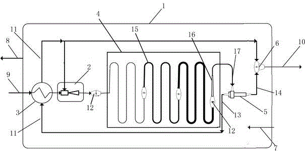
Figure 1 
Figure 2
Abstract
Description
technical field
[0001] The invention relates to a high-efficiency liquid heating gasification device and a method thereof, and belongs to the technical field of liquid gasification device equipment. Background technique
[0002] When gasifying a liquid substance, the current main method is to pass the liquid substance through a gasification device to exchange heat with the heat source substance, thereby raising the temperature from the liquid substance to the gaseous substance, but after the gasification obtained by this method The temperature of the gas is often lower than the temperature of the heat source material, and the temperature of the gas after gasification is only the same as the temperature of the heat source material in the most ideal state. The temperature of the heat source material is exchanged with the liquid material, or the gasified material is heated again, so it needs to consume a lot of heat, resulting in a large energy loss. At the same time, because t...
Examples
Embodiment Construction
[0019] In order to make the technical means, creative features, goals and effects achieved by the present invention easy to understand, the present invention will be further described below in conjunction with specific embodiments.
[0020] Such as figure 1 The high-efficiency liquid heating gasification device includes a housing 1, a jet vacuum pump 2, a regenerator 3, a heat exchange pipeline 4, a vortex tube 5 and a gas mixing tee 6, the housing 1 is a sealed structure, and its The heat source inlet 7, the heat source outlet 8, the liquid injection port 9 and the exhaust port 10 are respectively arranged on the two end faces of the corresponding position on the top, wherein the heat source inlet 7 and the exhaust port 10 are on the same side of the housing 1, and the heat source outlet 8 and the injection port The liquid port 9 is on the other side of the housing 1 , and the jet vacuum pump 2 , regenerator 3 , heat exchange pipeline 4 , vortex tube 5 and gas mixing tee 6 ar...