
Assembly structure of induction magnetic ring and shaft of motor rotor
A technology of induction magnetic ring and assembly structure, applied in the direction of electromechanical devices, electrical components, etc., can solve problems such as uneven distribution of magnetic force lines of induction magnetic ring, induction failure of Hall sensor, displacement or rupture of induction magnetic ring, etc., and achieve product stability Good performance, solve the problem of pressing and matching, and ensure the effect of product quality
Patent Information
- Authority / Receiving Office
- CN · China
- Patent Type
- Patents(China)
- Current Assignee / Owner
- Publication Date
- 2016-11-23
Smart Images
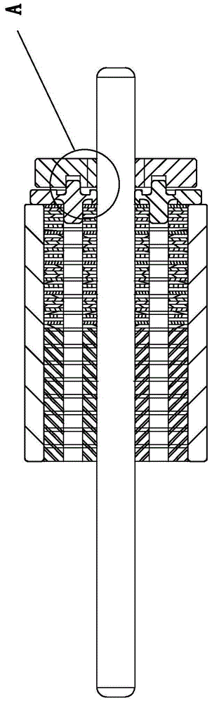
Figure 1 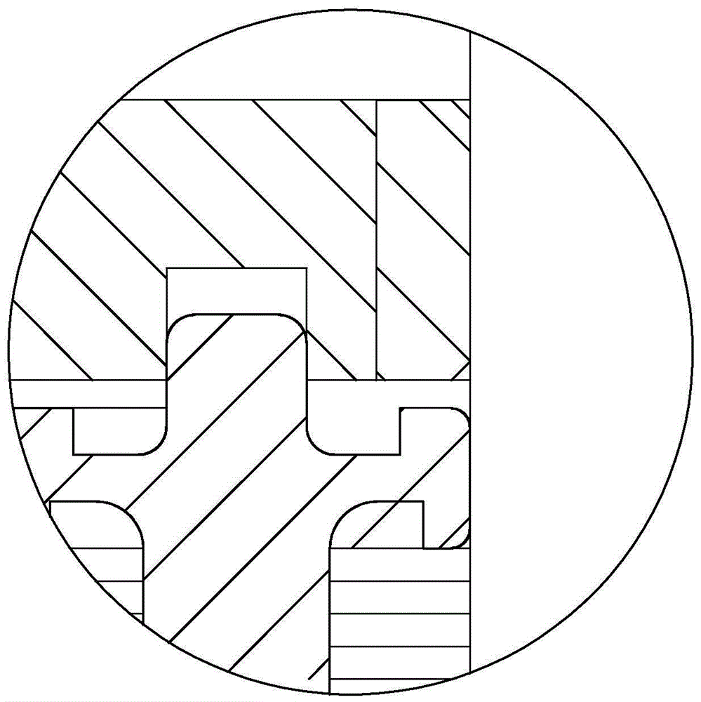
Figure 2 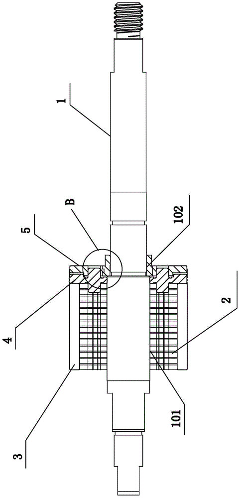
Figure 3
Abstract
Description
technical field
[0001] This product is an assembly structure of a motor rotor, especially relates to an assembly structure of an induction magnetic ring and a rotating shaft of a motor rotor, and belongs to the technical field of motor components. Background technique
[0002] The permanent magnet brushless DC motor not only has the advantages of high efficiency, good starting performance and good speed regulation performance of the commonly used DC brush, but also has the characteristics of long life, high reliability, low noise, and can be used in explosion-proof occasions. In actual production , is widely used.
[0003] However, in conventional permanent magnet brushless DC motors, the position accuracy of the induction magnetic ring cannot be guaranteed. Such as Picture 1-1 ,Such as Figure 1-2 As shown, the round optical axis is closely matched with the induction magnetic ring, and the position of the induction magnetic ring is controlled by the mold fixture. There ...
Examples
Embodiment Construction
[0026] The present invention will be further described below in conjunction with the accompanying drawings and specific embodiments, but not as a limitation of the present invention.
[0027] Such as Figure 2-1 to Figure 3-3 As shown, the assembly structure of the induction magnetic ring and the rotating shaft of the motor rotor, the motor is a permanent magnet brushless DC motor, and the assembly structure of the induction magnetic ring and the rotating shaft of the permanent magnet brushless DC motor rotor includes a stepped mode rotating shaft 1, a rotor iron Core 2, main magnet 3, plastic bushing 4 and induction magnetic ring 5.
[0028] The stepped mode shaft 1 includes a piercing portion A 101 and a piercing portion B 102, the rotor core 2 and the plastic bushing 4 are pierced on the piercing portion A 101 of the stepped mode shaft 1, and the induction magnetic ring 5 is threaded on the piercing part B 102 of the step mode rotating shaft 1; the plastic bushing 4 is arr...