
Foam Processing Equipment
A processing equipment and foam technology, which is applied in the field of foam processing, can solve problems such as easy cracking of foam, and achieve the effect of high safety and simple structure
Patent Information
- Authority / Receiving Office
- CN · China
- Patent Type
- Patents(China)
- Current Assignee / Owner
- Publication Date
- 2016-08-24
- Estimated Expiration
- Not applicable · inactive patent
Smart Images
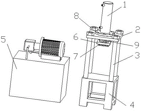
Figure 1 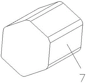
Figure 2 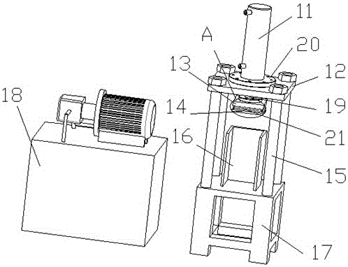
Figure 3
Abstract
Description
technical field
[0001] The invention relates to foam processing equipment, which belongs to the field of foam processing. Background technique
[0002] Please refer to figure 1 , figure 1 It is a structural schematic diagram of foam processing equipment in the prior art. The foam processing equipment in the prior art includes an oil pump assembly 5 , a hydraulic cylinder 1 , an upper platen 2 of a press, several pillars 3 , a base 4 and an upper mold 6 . The oil pump assembly 5 is connected with the hydraulic cylinder 1 to provide power for the hydraulic cylinder 1 . The upper platen 2 of the press is fixed on the base 4 through several pillars 3, the telescopic rod 9 of the hydraulic cylinder 1 passes through the center hole of the upper platen 2 of the press, and is fixedly connected with the upper platen 2 of the press through a connecting piece 8 . The telescopic rod 9 is connected with the upper mold 6 . Several drill bits 7 are fixed on the upper mold 6 . Please...
Examples
Embodiment Construction
[0018] Please refer to image 3 , image 3 It is a structural schematic diagram of the foam processing equipment of the present invention. The foam processing equipment includes: an oil pump assembly 18, a hydraulic cylinder 11, a press upper plate 12, a discharge plate 14, an upper die 13, a press lower plate 16, several pillars 15 and a base 17. The oil pump assembly 18 It is connected with the hydraulic cylinder 11 and is used to provide power for the hydraulic cylinder 11. The upper platen 12 of the press is fixed on the base 17 through several pillars 15, and the telescopic rod 19 of the hydraulic cylinder 11 passes through the center hole of the upper platen 12 of the press, and is fixedly connected with the upper platen 12 of the press through a connecting piece 20 . The telescopic rod 19 is connected with the upper mold 13 . The lower platen 16 of the press is arranged directly below the unloading plate 14 for fixing the foam to be processed.
[0019] Please refer...