
Thermally and/or mechanically actuated component wall of a fluid and/or gas-conveying component, in particular a cylinder head of a combustion engine
A mechanical load, internal combustion engine technology applied in the field of component walls to achieve the effect of reducing costs
Patent Information
- Authority / Receiving Office
- CN · China
- Current Assignee / Owner
- Publication Date
- 2015-06-24
Smart Images
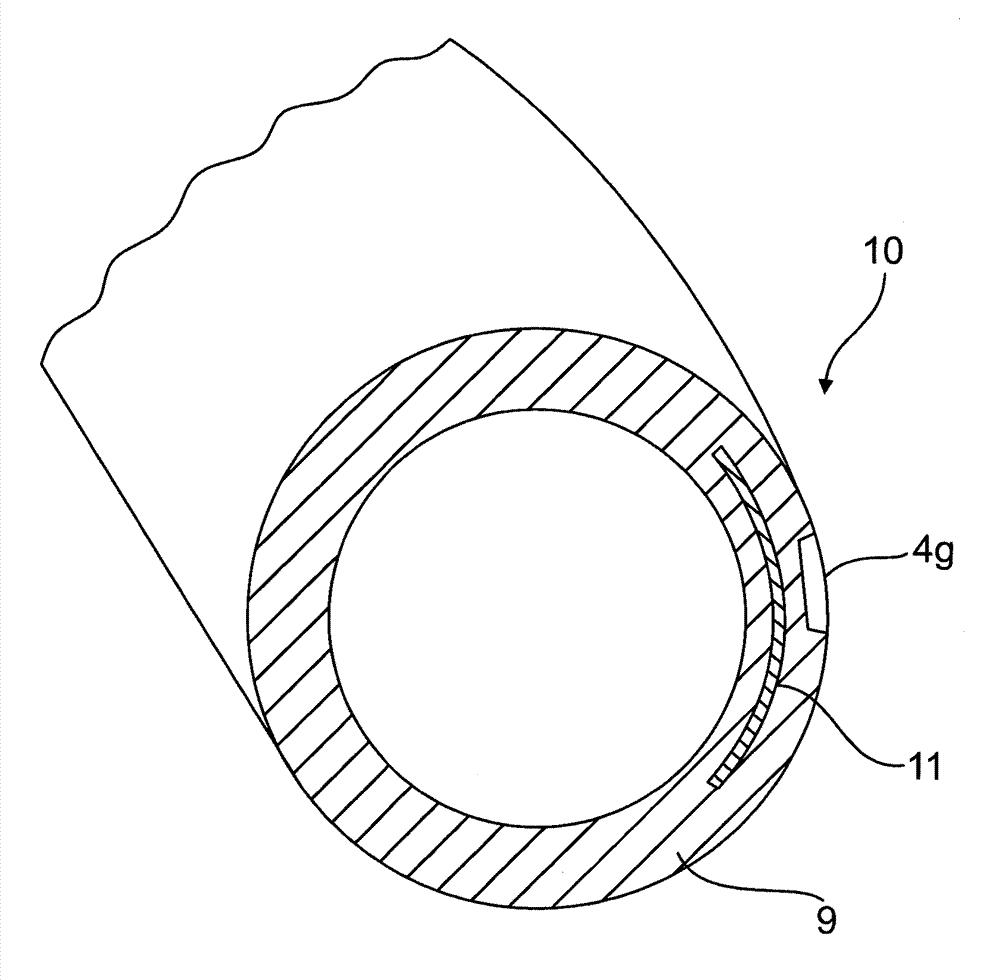
Figure 1 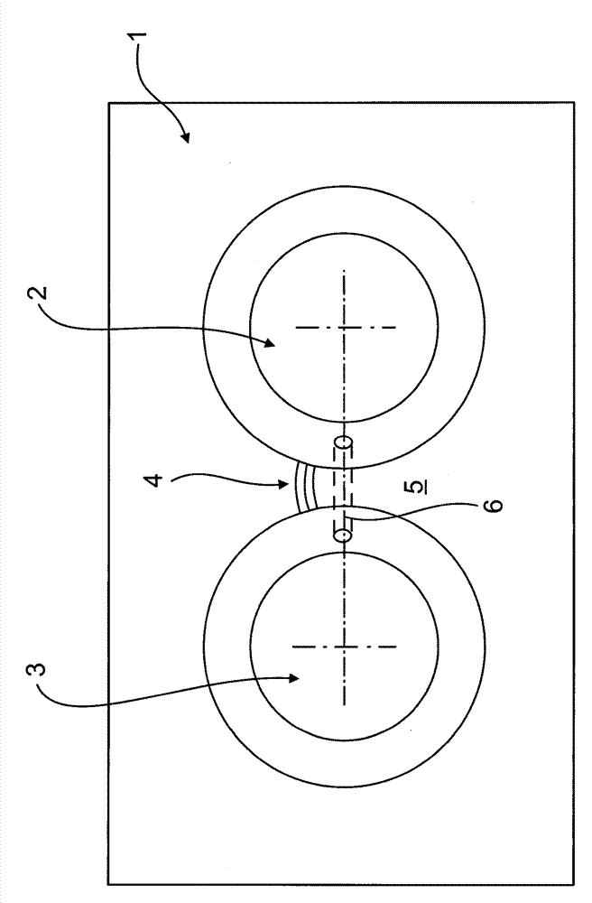
Figure 2 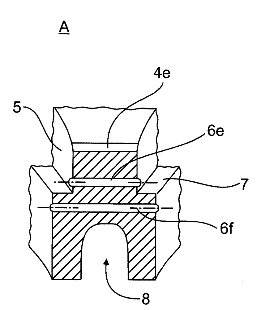
Figure 3
Abstract
Description
technical field
[0001] The invention relates to a thermally and / or mechanically loaded component wall of a fluid-conducting and / or gas-conducting component, in particular a cylinder head, of an internal combustion engine according to the preamble of claim 1 . Background technique
[0002] It is known that component walls of fluid-conducting or gas-conducting components, which are subjected to thermal or thermodynamic loads, tend to crack. The tendency to cracking can be mitigated in a manner known per se by solid structures and / or expansion joints and / or reduced temperature loading. However, especially in motor construction, these measures can only be used conditionally: the solid construction type is strictly limited due to the weight and cost situation. Likewise, the thermal load cannot be reduced practically, since the operation-related combustion in the internal combustion engine takes place at very high temperatures for thermodynamic reasons. The very high specific po...
Examples
Embodiment Construction
[0042] exist figure 1 A plan view of a partial area of a cylinder head 1 of an internal combustion engine is shown in the area of two adjacent valve seats 2 , 3 . As a crack initiation, a notch 4 is provided on the upper side of the bridging wall 5 , wherein the notch 4 is shifted a little relative to the smallest valve seat distance. Bore 6 runs as a crack stop parallel to the bridge wall surface in bridge wall 5 as connection of valve seats 2 , 3 below the cutout. For better visibility, the valve seats in all figures are shown without seat rings.
[0043] figure 2 A second alternative arrangement of the combination of crack initiation and crack arrestors is shown:
[0044] to this end, figure 2 A perspective plan view of a partial region of a four-valve cylinder head 1 with four valve seats 3 a , 3 b , 3 c , 3 d is shown. Here, compared to figure 1 The notches 4 a , 4 b , 4 c , 4 d are respectively arranged as crack initiations in the valve bridging region with t...