
freezer
A refrigeration device and refrigerant technology, applied in refrigerators, refrigeration components, refrigeration and liquefaction, etc., can solve the problems of increased compression power, increased specific enthalpy of evaporator inlet, and decreased performance coefficient, and can reduce dryness. Effect
Patent Information
- Authority / Receiving Office
- CN · China
- Patent Type
- Patents(China)
- Current Assignee / Owner
- Publication Date
- 2018-04-20
Smart Images
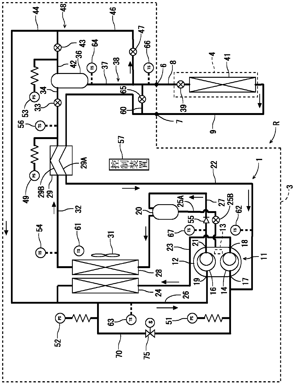
Figure 1 
Figure 2 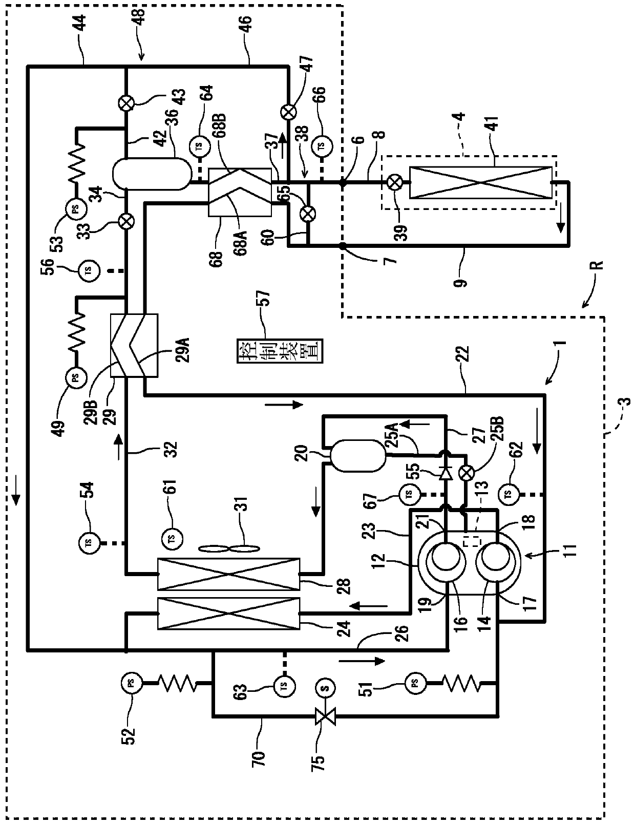
Figure 3
Abstract
Description
technical field
[0001] The invention relates to a refrigerating device whose refrigerant circuit is composed of a compression mechanism, a gas cooler, a main throttling mechanism and an evaporator, and the high-pressure side reaches supercritical pressure. Background technique
[0002] In the past, this type of refrigeration device constituted a refrigeration cycle by a compression mechanism, a gas cooler, and a throttling mechanism. The refrigerant evaporates, and the surrounding air is cooled by the evaporation of the refrigerant at this time. In recent years, Freon-based refrigerants have been gradually no longer used in such refrigerating devices due to natural environmental problems and the like. Therefore, the use of carbon dioxide, which is a natural refrigerant, as a substitute for Freon refrigerants is being developed. It is known that this carbon dioxide refrigerant is a refrigerant having a severe high-pressure difference and has a low critical pressure, and tha...
Examples
Embodiment 1
[0076] (1) Structure of refrigeration unit R
[0077] figure 1 It is a refrigerant circuit diagram of the refrigerating apparatus R according to one embodiment of the present invention. The refrigerating apparatus R in this embodiment includes a refrigerating machine unit 3 installed in an equipment room of a store such as a supermarket, and one or more (only one is shown in the drawing) display cabinets 4 installed in a sales floor of the store. These refrigerator units 3 and showcases 4 are connected by refrigerant pipes (liquid pipes) 8 and refrigerant pipes 9 via unit outlets 6 and unit inlets 7 to form a predetermined refrigerant circuit 1 .
[0078] The refrigerant circuit 1 of the embodiment uses carbon dioxide (R744) whose refrigerant pressure on the high-pressure side is equal to or higher than its critical pressure (supercritical) as a refrigerant. This carbon dioxide refrigerant is a natural refrigerant that is friendly to the global environment and considers flam...
Embodiment 2
[0141] Next, refer to image 3 and Figure 4 Another embodiment of the present invention will be described. also, image 3 and Figure 4 , labeled with figure 1 and figure 2 Parts with the same reference numerals are the same or have the same function. In the case of this example, in figure 1 The internal heat exchanger 68 is added to the refrigerant circuit 1. This internal heat exchanger 68 is provided in the refrigerant circuit 1 on the downstream side of the accumulator 36 and on the upstream side of the electric expansion valve 39 (primary throttling mechanism).
[0142] The internal heat exchanger 68 has a first flow path 68A and a second flow path 68B, and the first flow path 68A is interposed in the refrigerant introduction pipe 22 between the connection point with the bypass circuit 60 and the first flow path 29A of the heat exchanger 29 Among them, the second flow path 68B is interposed in the accumulator outlet pipe 37 before branching off from the liquid p...