
Visible grinding machine with automatic fine correction function
A micro-correction, grinding machine technology, applied in the direction of grinding machines, machine tools designed for grinding the rotating surface of workpieces, grinding machine parts, etc. The effect of deviation and quality improvement
Patent Information
- Authority / Receiving Office
- CN · China
- Patent Type
- Applications(China)
- Current Assignee / Owner
- Publication Date
- 2015-11-11
- Estimated Expiration
- Not applicable · inactive patent
Smart Images
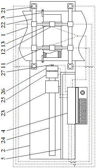
Figure 1
Abstract
Description
Technical field
[0001] The invention relates to the field of grinders, in particular to a visual automatic micro-correction grinder. Background technique
[0002] In the industrial production process, some parts with inner holes or tubular parts with outer square and inner circle need to be polished on the inner wall during the application process. However, the existing polishing device cannot perform precise polishing during the entire polishing process. Positioning and grinding are prone to deviations, which can cause irreversible damage to the parts, make the size of the parts inaccurate, and even cause the parts to be scrapped. Summary of the invention
[0003] In order to solve the above technical problems, the present invention provides a visual automatic micro-calibration grinder.
[0004] The technical solution adopted by the present invention to solve its technical problems is: a visual automatic micro-calibration grinder, which includes an operating table, a grinding whee...
Examples
Embodiment
[0015] Such as figure 1 As shown, a visual automatic micro-calibration grinder includes an operating table 1, a grinder table 2 arranged under the operating table 1, and a control system 4 arranged on the grinder table 2; the operating table 1 is an assembly line; both sides of the operation table 1 are provided with rotatable stop bars 3; on both sides of the operation table 1 are installed two Z-axis numerical control slide rails 21 on the grinder table 2; operation table 1 Between the two Z-axis numerical control slide rails 21 corresponding to both sides, an X-axis numerical control slide rail 22 is arranged across the operating table 1; two Y-axis numerical control slide rails 11 are erected between the two X-axis numerical control slide rails 22 The Y-axis numerical control slide rail 11 is provided with a clamping jaw slider 12; the clamping jaw slider 12 is fixed with a clamping jaw 13 for fixing the workpiece; the grinding wheel machine 2 is also fixed with a grinding ...