
Bearing arrangement
A facility and bearing technology, applied in the direction of bearings, bearing components, shafts and bearings, etc., can solve the problems of increased wear risk, increased wear risk of hydraulic sealing system, etc., and achieve the effect of reducing wear and tear
Patent Information
- Authority / Receiving Office
- CN · China
- Current Assignee / Owner
- Publication Date
- 2016-01-27
Smart Images
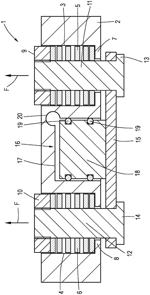
Figure 1 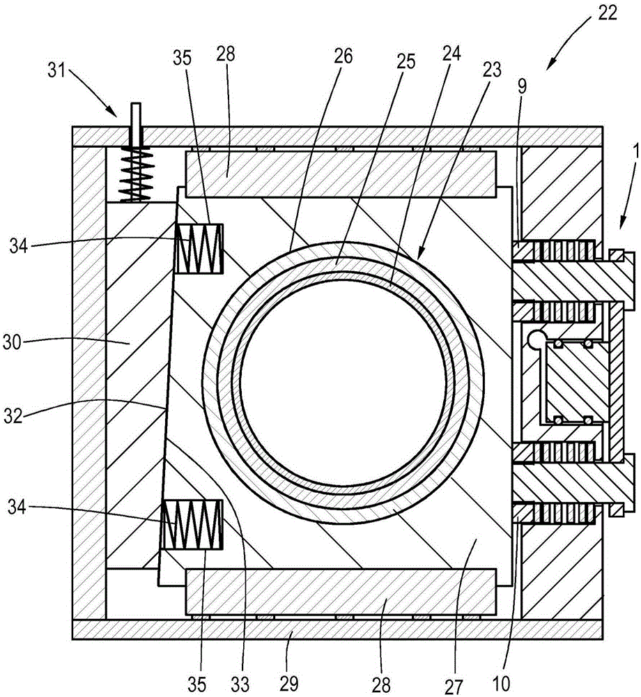
Figure 2
Abstract
Description
technical field
[0001] The present invention relates to a bearing arrangement for a component supported in rotation about an axis, such as a roller, roller, drum or shaft, which bearing arrangement comprises at least one rolling bearing housed in a bearing housing, which bears via at least A linear guide is movably supported in a linearly movable manner within the installation housing, and the bearing installation includes adjustment means for linearly adjusting the bearing housing between a rest position and an operating position perpendicular to the axis . Background technique
[0002] Bearing arrangements of this type with linearly adjustable rolling bearings are used, for example, in presses for setting and removing rolls. An example for such a bearing arrangement is known from DE 10145322 A1. In this document, a pressure-loaded hydraulic cylinder is provided as the adjusting device in order to move the bearing housing together with the roller bearing, ie towards the s...
Examples
Embodiment Construction
[0019] figure 1 An adjusting device 1 according to the invention is shown, which comprises a housing 2 in which, in the exemplary embodiment shown, two cylindrical receptacles 3, 4 are arranged, in which are respectively accommodated Spring elements 5,6. These are high-efficiency springs with rectangular coil cross-sections, which can generate high adjusting forces. The springs are supported with one end on the respective bases 7 , 8 of the recesses 3 , 4 . They are supported at the other end on pressure pieces 9 , 10 which are respectively arranged on bolts 11 , 12 arranged in receptacles 3 , 4 , in particular screwed thereon. The spring elements 5 , 6 are pretensioned, and they make it possible to exert a pressing force, as indicated by the two arrows F, on the pins 11 , 12 together with the piston disks 9 , 10 , which push them out of the housing 2 . Press outward. A bearing housing is associated with these two pins 11 , 12 together with the piston disks 9 , 10 , in whi...