
Oppositely penetrating steel bar and oppositely penetrating vertical insert plate type beam column two-way rigid joint
A technology for piercing steel rods and inserts, which is applied in construction, building construction, etc., can solve the problems of difficult casting of rigid joints, low level of industrialization, etc., and achieves the effect of processing difficulty, cost reduction, and simple processing.
Patent Information
- Authority / Receiving Office
- CN · China
- Current Assignee / Owner
- Publication Date
- 2016-04-27
Smart Images
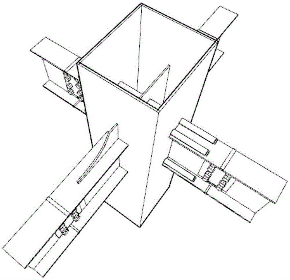
Figure 1 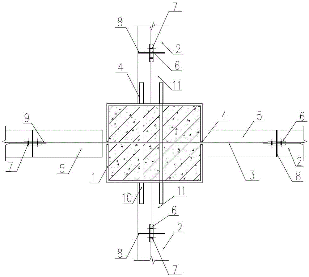
Figure 2 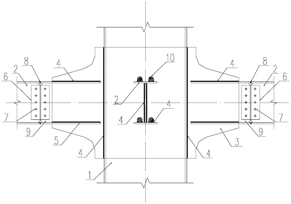
Figure 3
Abstract
Description
technical field
[0001] The invention relates to a beam-column joint, in particular to a beam-column two-way rigid joint of the cross-piercing steel bar and cross-cut vertical plate type, which can be widely used in the connection between H-shaped steel beams and steel pipe concrete columns in multi-high-rise steel structures. Just connected. Background technique
[0002] In the multi-story steel structure, the steel beams are mostly H-shaped steel beams, and the steel columns are mostly rectangular steel tube concrete columns. The rigid connection of steel beams and steel columns is the most basic measure to provide the overall rigidity and seismic performance of the structure. At present, the commonly used rigid connection node is to set a diaphragm at the position corresponding to the beam flange of the steel column. The internal force of the steel beam flange is transmitted to the steel column through the diaphragm. This connection method can provide the required rigidit...
Examples
Embodiment 1
[0046]An embodiment of the present invention is figure 1 and figure 2 As shown, it includes concrete-filled steel pipe column 1, steel beam 2, insert plate 3, steel rod 11, insert plate corbel and steel rod corbel, and two mutually perpendicular directions of steel pipe concrete column 1 are respectively inserted with insert plate 3 and four steel rod 10.
[0047] The wall plate of the steel pipe concrete column 1 is provided with a strip groove where the insert plate 3 penetrates, and the insert plate 3 passes through the strip groove and is welded to the wall plate through the weld seam 4 . The inserting plate 3 runs through both ends of the steel pipe concrete column 1 and connects to the inserting plate corbel: there is an axial strip groove in the middle of one end of the inserting plate corbel flange 5, and the inserting plate 3 is inserted in the inserting plate corbel The flange 5 is in the strip groove and welded with the plate corbel flange 5 through the weld 4, t...
Embodiment 2
[0050] Example 2 as figure 1 and figure 2 As shown, the difference from Embodiment 1 is that four steel bars 10 are welded on the lower surface of the steel bar corbel flange 1 at the same time, as Figure 4 and Figure 7 shown.
Embodiment 3
[0052] Example 3 as figure 1 and figure 2 As shown, the difference from Embodiment 1 is that four steel rods 10 are inserted and welded inside the steel rod corbel flange 1 at the same time, as Figure 5 and Figure 8 shown. The center of the steel rod 10 can be aligned with the center of the steel rod corbel flange 1, where the steel rod corbel flange 1 is provided in the strip groove in the middle along the axial direction and welded by the weld seam 4, and the steel rod 10 is inserted into the steel rod The position of the corbel flange 1 is slotted and then welded by the weld seam.