
Die for punching irregular edge-turned holes in batch on steel plate
An irregular and edge-turning technology, applied in the direction of perforation tools, manufacturing tools, metal processing equipment, etc., can solve the problems of low production efficiency, long cycle and unsuitable for mass production, etc., to improve production efficiency, reduce labor, reduce Workflow Effects
Patent Information
- Authority / Receiving Office
- CN · China
- Patent Type
- Applications(China)
- Current Assignee / Owner
- Publication Date
- 2016-06-01
- Estimated Expiration
- Not applicable · inactive patent
Smart Images
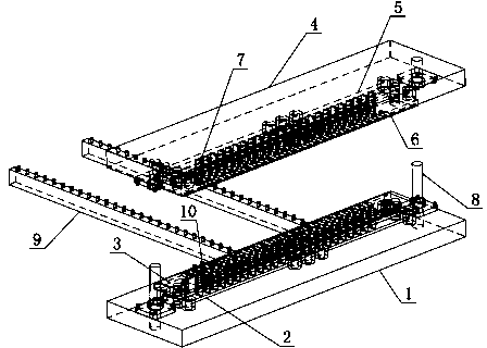
Figure 1 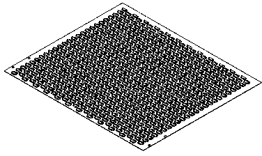
Figure 2
Abstract
Description
technical field
[0001] The invention relates to a mechanical processing device, in particular to a mold for batch punching irregular edge holes on steel plates. Background technique
[0002] At present, when punching holes on ordinary punching machines, only holes with regular diameters can be punched. When processing parts, it is required to punch irregular holes along the edges, and it is necessary to convert two or more sets of molds to process the shape. This processing method The production efficiency is low, and the cycle is long, which is not suitable for mass production. Contents of the invention
[0003] The technical problem to be solved by the present invention is that batches of irregular turning holes can be processed without changing moulds, thereby improving production efficiency and reducing labor.
[0004] In order to solve the above-mentioned technical problems, the technical solution adopted by the present invention is: one set of molds for punching irr...
Examples
Embodiment Construction
[0014] The present invention will be further described below in conjunction with the accompanying drawings: the mold for punching irregular turning holes in batches on the steel plate includes a bottom plate (1), an upper plate (4), a lower fixing plate (2), a lower supporting plate (3), an upper fixing plate Plate (5), upper support plate (6), irregular turning punch (7), guide post (8), positioning clamp (9) and positioning pin (10).
[0015] Install the lower supporting plate (3) on the lower fixing plate (2), then install it on the bottom plate (1), and install the punch (7) along the irregular hole on the upper supporting plate (6), and then connect it with the upper The fixed plates (5) are installed together, and then they are installed together on the upper plate (4), and the lower die is matched with the cutting edge of the upper die by debugging. The guide post (8) connects the bottom plate (1) and the upper plate (4), so that the upper plate (4) can move linearly in...