
A nail feeding device for automatic drilling and riveting machine
An automatic drilling riveting machine and nail feeding technology, which is applied in the field of aviation manufacturing, can solve problems such as unfavorable production efficiency, large nail feeding structure, and complicated nail feeding process, and achieve the effect of compact structure and guaranteed clamping effect
Patent Information
- Authority / Receiving Office
- CN · China
- Patent Type
- Patents(China)
- Current Assignee / Owner
- Publication Date
- 2017-10-31
Smart Images
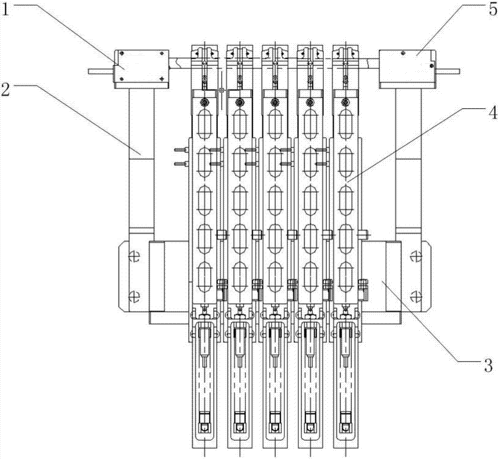
Figure 1 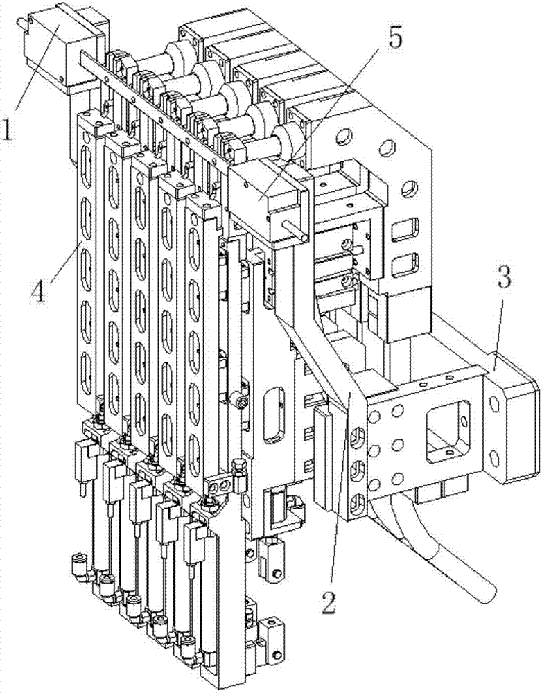
Figure 2 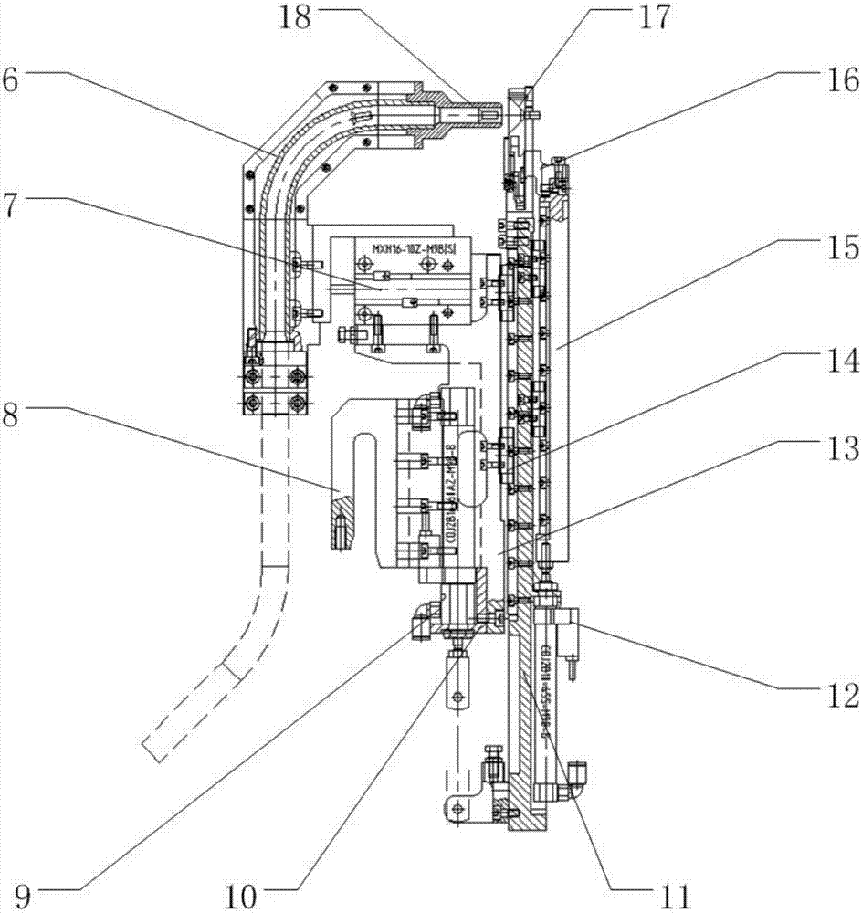
Figure 3
Abstract
Description
technical field
[0001] The invention relates to the field of aviation manufacturing, in particular to a nail feeding device for an automatic drilling and riveting machine. Background technique
[0002] In the assembly of metal components such as aircraft panels, riveting is still one of the most important connection methods at present, occupying a huge workload. Traditional manual riveting has poor working conditions and low production efficiency. The quality of riveting depends heavily on the experience and technology of workers, and does not meet the development requirements of aircraft digital assembly. Therefore, it is imperative to use automatic drilling and riveting machines to replace manual operations. However, the principle and structure of high-end automatic drilling and riveting machines are quite complicated. At present, only a few manufacturers in Europe and the United States have the ability to develop and manufacture, such as EI, GEMCOR, BROETJE, etc. The deve...
Examples
Embodiment Construction
[0033] The specific embodiments of the present invention will be described below in conjunction with the accompanying drawings.
[0034] Such as Figure 1 to Figure 5 As shown, a nail feeding device for an automatic drilling and riveting machine is characterized in that it includes a base 3, a delivery elbow 6, a nail output cylinder 7, a fork-shaped mounting seat 8, a first telescopic cylinder 9, a cylinder bracket 10, a first telescopic layer 11. Second telescopic cylinder 12, base rail seat 13, miniature linear guide rail 14, second telescopic layer 15, push nail head 16, nail output head 18, laser micrometer launcher 1, sensor bracket 2, laser micrometer The receiving end 5 , the cover plate 19 , the nail base plate 20 , the first nail auxiliary claw 21 , the first spring seat 22 , the second nail nail auxiliary claw 23 , the spring 24 , and the second spring seat 25 . Wherein, the second telescopic layer 15 is connected to the first telescopic layer 11 through the guide ...