
Circulation structure of injection molding machine
A technology of injection molding machine and barrel, applied in the field of circulation structure of injection molding machine, can solve problems such as production difficulties, and achieve the effect of preventing long-term heat discoloration
Patent Information
- Authority / Receiving Office
- CN · China
- Patent Type
- Applications(China)
- Current Assignee / Owner
- Publication Date
- 2016-09-07
Smart Images
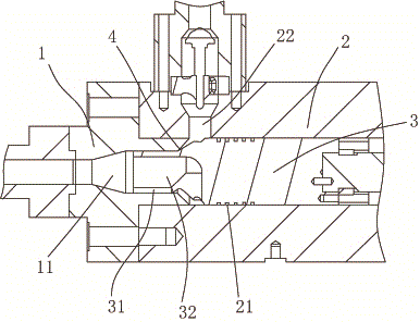
Figure 1 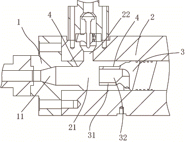
Figure 2
Abstract
Description
technical field
[0001] The invention belongs to the technical field of injection molding machines, in particular to a circulation structure of injection molding machines. Background technique
[0002] For a two-stage structure injection molding machine, the parts where the molten plastic raw materials flow through are the most likely to accumulate material is the position of the plunger head and the front barrel. In the current structure, the melted plastic raw material flows in from the raw material channel on the side of the machine barrel, and will directly lead to the central hole of the front machine barrel. In this way, there are many parts on the outside of the plunger head that cannot produce a flushing effect. The inner side of the front barrel also has poor flushing effect. The raw materials in these parts will accumulate for a long time. And because of the production process, these parts are continuously heated. In this way, after a few hours or a few days, th...
Examples
Embodiment Construction
[0011] The present invention will be described in further detail below in conjunction with accompanying drawing and specific embodiment: see Figure 1 to Figure 2 , a circulation structure of an injection molding machine, comprising a front barrel 1 and a barrel 2, the front barrel 1 is provided with a feeding channel 11, the barrel 2 is provided with a plunger channel 21, and the plunger The channel 21 is connected with the feed channel 11, the plunger channel 21 is provided with a plunger 3, the side of the barrel 2 is provided with a feed port 22, and the top of the plunger 3 is provided with a diameter smaller than the inlet port. The boss 31 of the material channel 11, the plunger 3 and the boss 31 are provided with two openings located at the top of the boss 31 and a number of first passages 32 on the side walls of the plunger 3; when the boss When the head 31 fully extends into the feed channel 11 , the opening of the side wall of the plunger 3 communicates with the fee...