
A clamp type reducing pipe connection device
A connection device and clamp-type technology, which is applied in the direction of sleeve/socket connection, pipe/pipe joint/pipe fitting, passing element, etc., to achieve the effect of simple structure, convenient installation and good sealing performance
Patent Information
- Authority / Receiving Office
- CN · China
- Patent Type
- Patents(China)
- Current Assignee / Owner
- Publication Date
- 2019-04-09
Smart Images
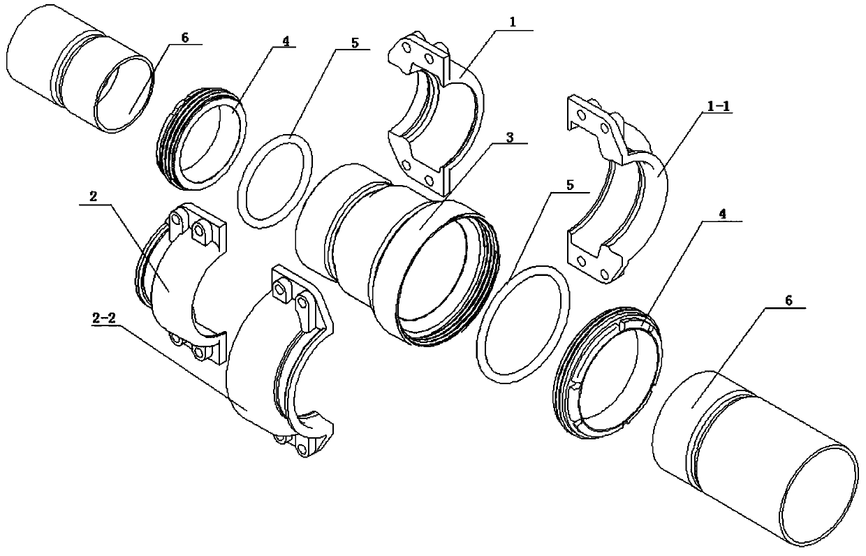
Figure 1 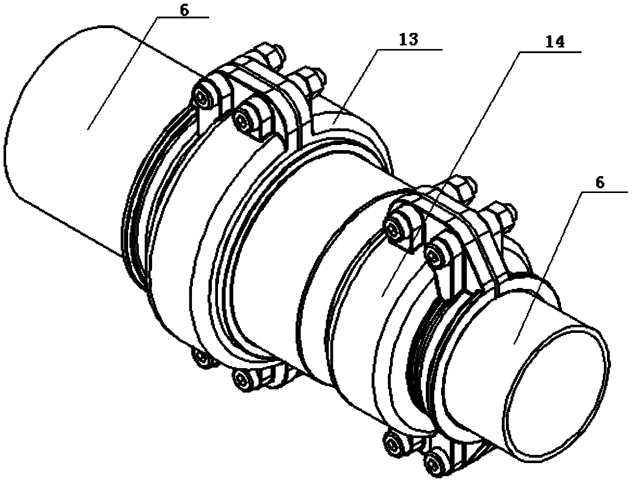
Figure 2 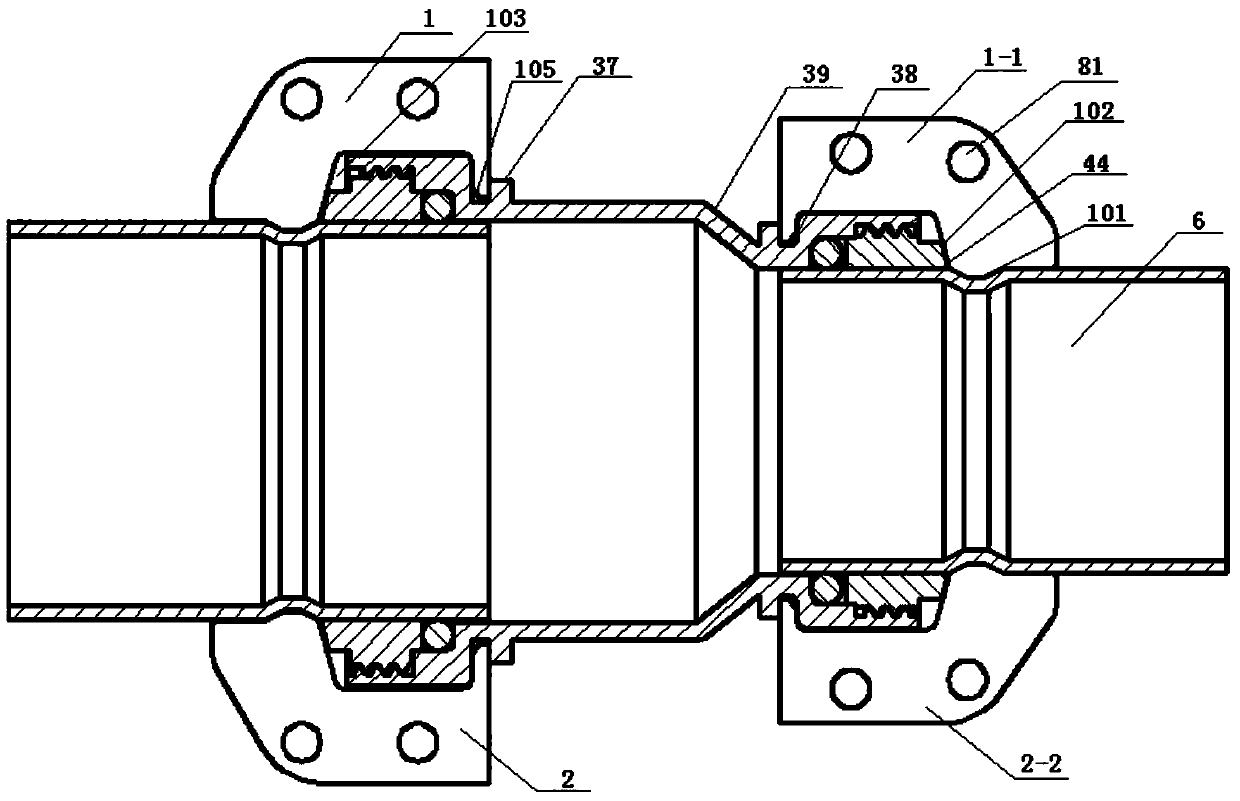
Figure 3
Abstract
Description
technical field
[0001] The invention relates to a pipeline conveying system, in particular to a clamp-type variable-diameter pipeline connection device. Background technique
[0002] In large-scale compressed air or fluid pipeline systems, it is usually necessary to use larger diameter delivery pipelines in conjunction with small diameter delivery pipelines. Small pipe joints can be used for small diameter pipes, but this type of pipe joint is not suitable For pipelines with larger diameters, the connection strength cannot meet the requirements of pipelines with larger diameters.
[0003] For the connection devices of larger diameter pipelines, the flange connection is generally used at present, which needs to be welded on site and then leak tested. If the weld has welding defects such as slag inclusion, it needs to be reworked, which has higher requirements for the on-site installation workers. The installation efficiency is low, and it is not easy to disassemble; in the p...
Examples
Embodiment Construction
[0029] The application will be further explained below in conjunction with the accompanying drawings.
[0030] Such as Figure 1-3 Shown is a schematic diagram of the structure of the clamp-type reducing pipe connection device provided by the application. It can be seen from the figure that the connection device shown includes an outer shell and a sealing device, and the outer shell is composed of a first ring body 13 and a second ring body 14, the first ring body 13 and the second ring body 14 are respectively composed of two half ring bodies: the first half ring body 1 and the second half ring body 2, the third half ring body 1-1 and the fourth half ring body 2-2 structure, the first half-ring body 1 and the second half-ring body 2 and the third half-ring body 1-1 and the fourth half-ring body 2-2 are connected by locking members, inside the four half-ring bodies The walls are respectively provided with semi-annular installation grooves 103, and the two half-annular bodies ...