
Double-headed stud automatic tightening device
A technology of automatic tightening device and double-ended stud, which is applied in metal processing, metal processing equipment, manufacturing tools, etc., can solve problems such as no discovery, and achieve the effect of improving work efficiency
Patent Information
- Authority / Receiving Office
- CN · China
- Patent Type
- Patents(China)
- Current Assignee / Owner
- Publication Date
- 2018-07-20
Smart Images
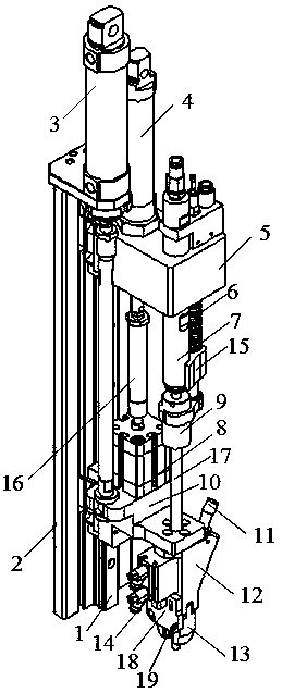
Figure 1
Abstract
Description
technical field
[0001] The invention belongs to a device for tightening a stud, in particular to an automatic tightening device for a double-ended stud. Background technique
[0002] Double-ended studs refer to cylindrical fasteners with threads at both ends, which are widely used in electric power, chemical industry, oil refining, valves, railways, bridges, steel structures, automobile and motorcycle parts, machinery, boiler steel structures, hanging towers, large Span steel structures and large buildings, etc. The double-ended stud connection is to screw one end of the double-ended stud into the screw hole of one of the connected parts, and the other end passes through the through hole of the other connected part, then put on the washer and tighten the nut. The assembly of double-ended studs needs to be completed with the help of special tools. The usually used double-ended stud tightener is to rely on external force to rotate the screw sleeve, screw the tail end of the d...
Examples
Embodiment Construction
[0024] The double-ended stud automatic tightening device of the present invention will be described in detail below in conjunction with the drawings and embodiments of the description:
[0025] As shown in the figure, a double-headed stud automatic tightening device includes a guide rail 1 installed on a bracket 2, a main linear cylinder 3 is arranged on the top of the bracket 2, and the lower end of the piston rod of the main linear cylinder 3 is fixedly connected to the lower fixing plate 10. The auxiliary linear cylinder 4 is installed on the upper end surface of the upper fixed plate 5, and its piston rod stretches out the upper fixed plate 5 downwards; the retraction cylinder 8 is fixed on the upper end surface of the lower fixed plate 10, and the piston rod and the retracted The piston rod of the cylinder 8 is connected through the connecting rod 16; the tightening cylinder 15 is installed on the upper end surface of the upper fixed plate 5, and the lower end of the pisto...