
Lateral extrusion-push type soil-covering pressing monomer
A soil-covering and single-body technology, which is applied in planting methods, excavation/covering trenches, application, etc., can solve problems such as uncoordinated cooperation between the soil covering device and the suppression wheel, large variation in seed position, uneven suppression pressure, etc., and achieves improved Consistency of plant spacing, uniform distribution of suppression pressure, uniform suppression effect
Patent Information
- Authority / Receiving Office
- CN · China
- Current Assignee / Owner
- Publication Date
- 2017-03-22
- Estimated Expiration
- Not applicable · inactive patent
Smart Images
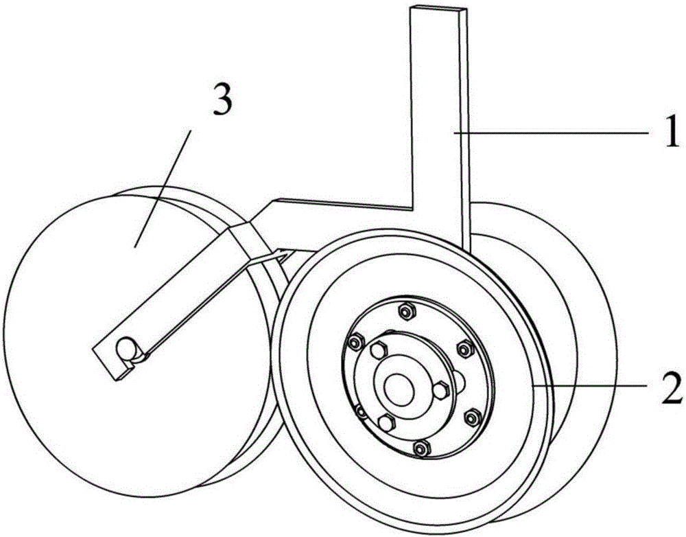
Figure 1 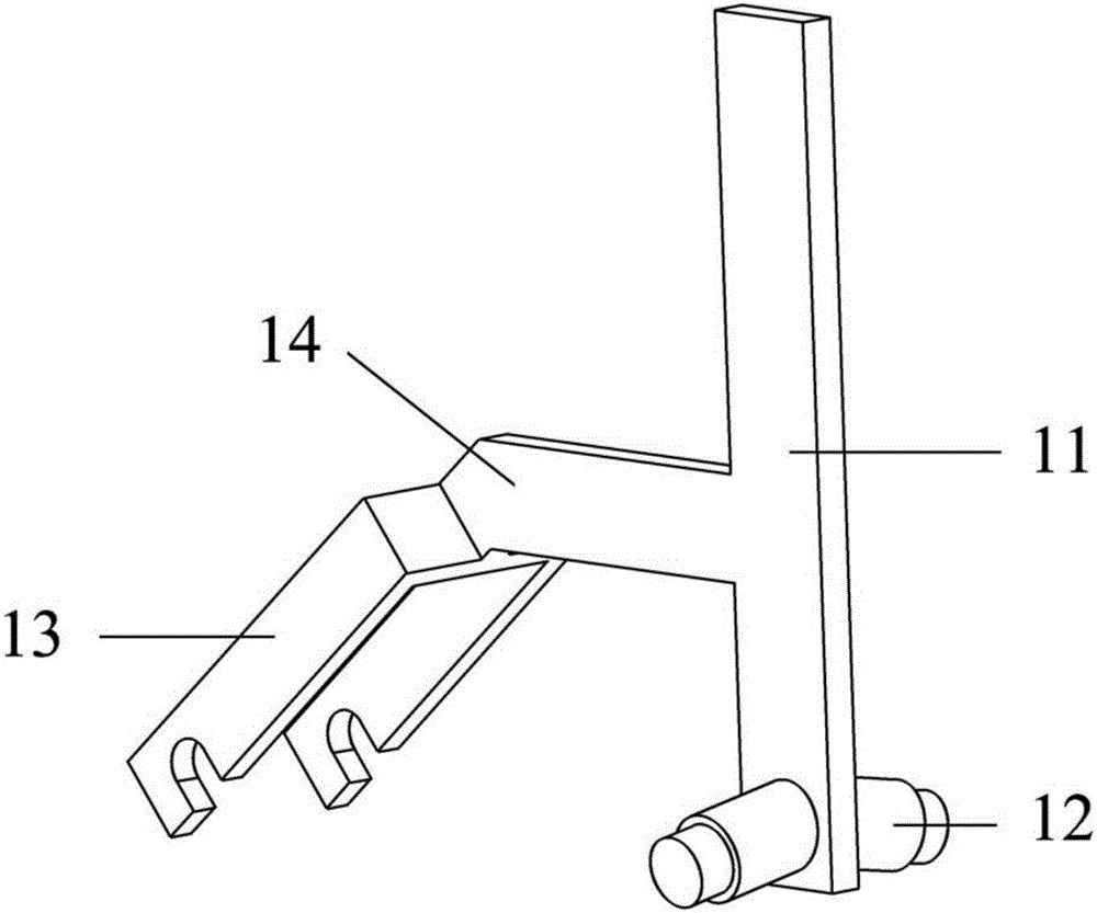
Figure 2 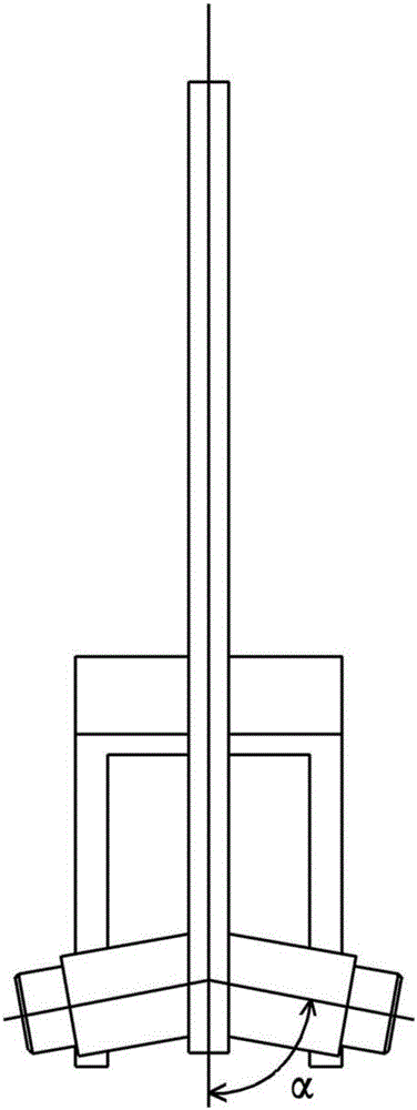
Figure 3
Abstract
Description
technical field
[0001] The invention belongs to the field of agricultural machinery, and in particular relates to a side pushing type soil-covering compacting unit. Background technique
[0002] The covering and suppressing unit is one of the main working parts of the precision seeder. It is used to cover the seeds in the seed ditch tightly after sowing. It is required that the amount of covering soil is appropriate and uniform, and there is no phenomenon of bulldozing and blocking the soil. The seed bed after suppression is flat. No scaly cracks. There are mainly four kinds of existing cover devices, including: push ring type cover device, figure-eight cover device, double disc type cover device and squeeze type cover device. The first three kinds of soil covering devices need to be used in conjunction with the pressing wheel. The covering soil is large and uniform, and has a wide range of applications. However, it is easy to cover the seed ditch with surface dry soil duri...
Examples
Embodiment Construction
[0025] see Figure 1 to Figure 7 , the present invention is made up of frame 1, earth-covering device 2 and trapezoidal groove suppressing wheel 3, and earth-covering device 2 is installed in frame 1 front, and left and right is symmetrical, and trapezoidal groove suppressing wheel 3 is installed in the rear of frame 1.
[0026] The frame 1 is left-right symmetrical in the advancing direction, and is made up of a handle 11, a stepped shaft 12, a pressing wheel support 13 and a support plate 14. The frame 1 is made of a plate with a thickness of 4-8mm. Two stepped shafts 12 are respectively fixed on both sides of the handle 11 by welding, and they are symmetrically distributed in the forward direction. On a vertical plane, the angle between the axis of the stepped shaft 12 and the mounting plane of the handle 11 is α, where 2π / 5≤α<π / 2. The stepped shaft 12 has two sections. The section fixed to the installation plane of the handle 11 is the large end of the stepped shaft 12, a...