
Direct current brushless motor provided with brake and used for clutch
A brushless DC and clutch technology, applied in the field of electric motors, can solve the problems of inability to lock the mechanism, rebound, affecting the positioning accuracy of the controller, etc., and achieve the effects of improving production efficiency, improving waterproof, and ensuring the applicable environment and service life.
Patent Information
- Authority / Receiving Office
- CN · China
- Current Assignee / Owner
- Publication Date
- 2017-06-13
Smart Images
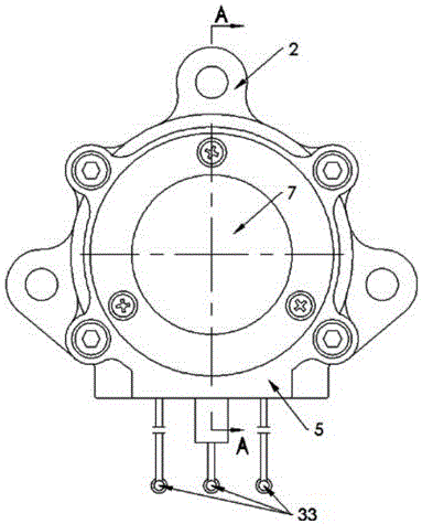
Figure 1 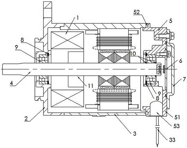
Figure 2 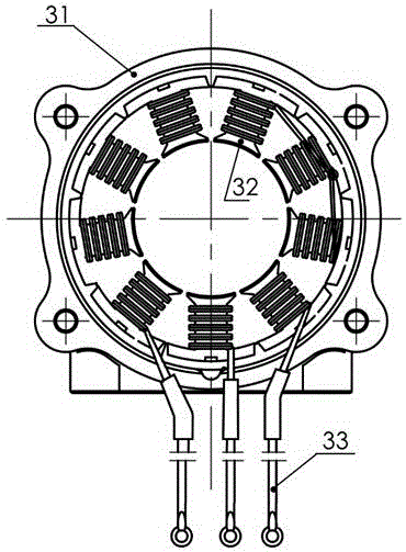
Figure 3
Abstract
Description
technical field
[0001] The invention relates to the technical field of motors, in particular to a DC brushless motor for a clutch with a brake. Background technique
[0002] The existing ATM clutch actuator uses a brushless DC motor without an electromagnetic brake. The motor cannot lock the mechanism when it is not working, and rebound phenomenon will occur, which will affect the positioning accuracy of the controller. Contents of the invention
[0003] In view of the above disadvantages, the object of the present invention is to provide a DC brushless motor with a brake, which has the advantages of locking the mechanism when the motor is not working, and ensuring the stability of the motor's rotational position.
[0004] The technical solution of the present invention is realized in the following manner: a DC brushless motor for a clutch with a brake, which consists of an electromagnetic brake, a front end cover assembly, a stator assembly, a rotor assembly, an end cover...
Examples
Embodiment Construction
[0018] Depend on figure 1 , figure 2 It is known that a DC brushless motor for a clutch with a brake is composed of an electromagnetic brake 1, a front end cover assembly 2, a stator assembly 3, a rotor assembly 4, an end cover assembly 5, a sensor assembly 6 and a sensor protection cover 7 Composition; the left end of the stator assembly 3 is fixed with a front end cover assembly 2, the right end of the stator assembly 3 is fixed with an end cover assembly 5, the sensor assembly 6 is installed on the end cover assembly 5, and the sensor protection cover 7 is fixed on the end cover assembly 5 to cover the sensor assembly 6; the front end cover assembly 2 and the end cover assembly 5 are respectively fixed with a bearing 9 through a snap spring 8; the left end of the rotor assembly 4 It is connected with the bearing 9 on the front end cover assembly 2, and its right end is connected with the bearing 9 on the end cover assembly 5, and is limited by the circlip II10 provided on...