
A new energy vehicle charging pile with high safety
A new energy vehicle, safety technology, applied in the direction of electric vehicle charging technology, charging stations, electric vehicles, etc., can solve the problems of bulky charging piles, fire, and occupying a lot of land, so as to improve charging safety and stability Effect
Patent Information
- Authority / Receiving Office
- CN · China
- Patent Type
- Patents(China)
- Current Assignee / Owner
- Publication Date
- 2018-06-05
Smart Images
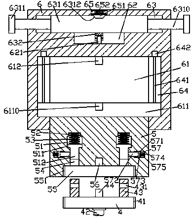
Figure 1 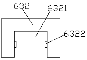
Figure 2 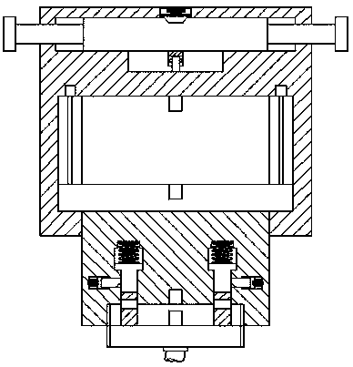
Figure 3
Abstract
Description
technical field
[0001] The invention relates to the technical field of new energy vehicle charging, in particular to a new energy vehicle charging pile with high safety. Background technique
[0002] As a green transportation tool with broad development prospects, electric vehicles will be popularized at an extremely fast speed, and the future market prospects are also extremely huge. However, electric vehicles need to be charged through charging piles before they can continue to be used. Charging piles are installed in public buildings (public buildings, shopping malls, public parking lots, etc.) and residential parking lots or charging stations, and can charge various types of electric vehicles according to different voltage levels. The input end of the charging pile is connected to the AC power grid, and the output end is equipped with a charging head for charging electric vehicles. The existing charging pile is bulky and occupies a lot of land, which limits its use, low...
Examples
Embodiment Construction
[0022] Such as Figure 1-Figure 8 As shown, a high-safety new energy vehicle charging pile of the present invention includes a body 6 and a charging gun head 4 provided at the bottom of the body 6. The bottom of the body 6 is provided with an accommodation chamber 61, and the accommodation chamber The left and right sides of 61 are provided with sliding grooves 64, and the described sliding grooves 64 are provided with screw rods 641, the top of the described screw rods 641 is connected with the power of the motor 642, and the accommodating cavity 61 is provided with moving beams 611. Both ends of the beam 611 extend into the sliding groove 64 and are threadedly connected with the screw rod 641. The bottom of the moving beam 611 is provided with a connecting block 5, and the bottom of the connecting block 5 passes through the bottom wall of the body 6 and slides Cooperate with the connection, the inside of the connecting block 5 is left and right symmetrically provided with a ...