
Tool capable of being automatically overturned
An automatic turning and tooling technology, applied in metal processing and other directions, can solve the problems of manual turning error, human safety injury, high labor cost, etc., and achieve the effect of preventing over-movement, ensuring safe production and reducing labor intensity
Patent Information
- Authority / Receiving Office
- CN · China
- Patent Type
- Applications(China)
- Current Assignee / Owner
- Publication Date
- 2017-09-01
Smart Images
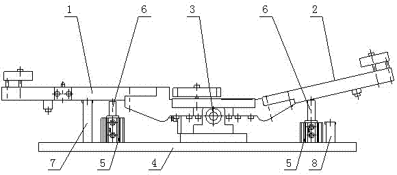
Figure 1
Abstract
Description
Technical field
[0001] The invention relates to the technical field of automation equipment, in particular to a tool that can be automatically turned over with simple structure, low cost, high production efficiency and high safety factor. Background technique
[0002] In the past, when processing zigzag-shaped workpieces, such as zigzag doors, after processing one side and before processing the other side, it was necessary to manually flip the tooling, and manually change the angle during half of the processing. This is not only manual The error of overturning has great potential harm to the safety of life; in addition, manual overturning angle needs to be stopped, which wastes a lot of time, and manual overturning increases the risk of collision. It can be seen that manual turning tooling has low production efficiency, high labor intensity, high labor costs for workers, and large safety hazards.
[0003] Therefore, when both sides of the zigzag-shaped part need to be processed on...
Examples
Embodiment 1
[0019] Such as figure 1 Shown:
[0020] A tooling that can be automatically turned over, comprising a left tooling plate 1, a right tooling plate 2, a rotating shaft 3, and a base 4; the left tooling plate 1 and the right tooling plate 2 are detachably fixedly connected, and the rotating shaft 3 Set at the lower part of the connection point of the left tooling plate 1 and the right tooling plate 2, the left tooling plate 1 and the right tooling plate 2 can be turned around the rotating shaft 3; the base 4 is set at the lower part of the rotating shaft 3; Both the left tooling plate 1 and the right tooling plate 2 are provided with a cylinder 5, the cylinder seat of the cylinder 5 is fixed on the base 4, and the upper part of the cylinder shaft is provided with a left tooling plate 1 and a right tooling plate 2 The ejector rod 6; the outer side of the cylinder 5 under the left tooling plate 1 and the right tooling plate 2 is also provided with a left limit plate 7 and a right lim...