
Device for automatic deceleration of shaft parts
A kind of shaft parts, automatic technology, applied in the direction of drum brake, brake type, gear transmission mechanism, etc., can solve the problems of complex structure and inconvenient maintenance
Patent Information
- Authority / Receiving Office
- CN · China
- Patent Type
- Patents(China)
- Current Assignee / Owner
- Publication Date
- 2018-11-27
Smart Images
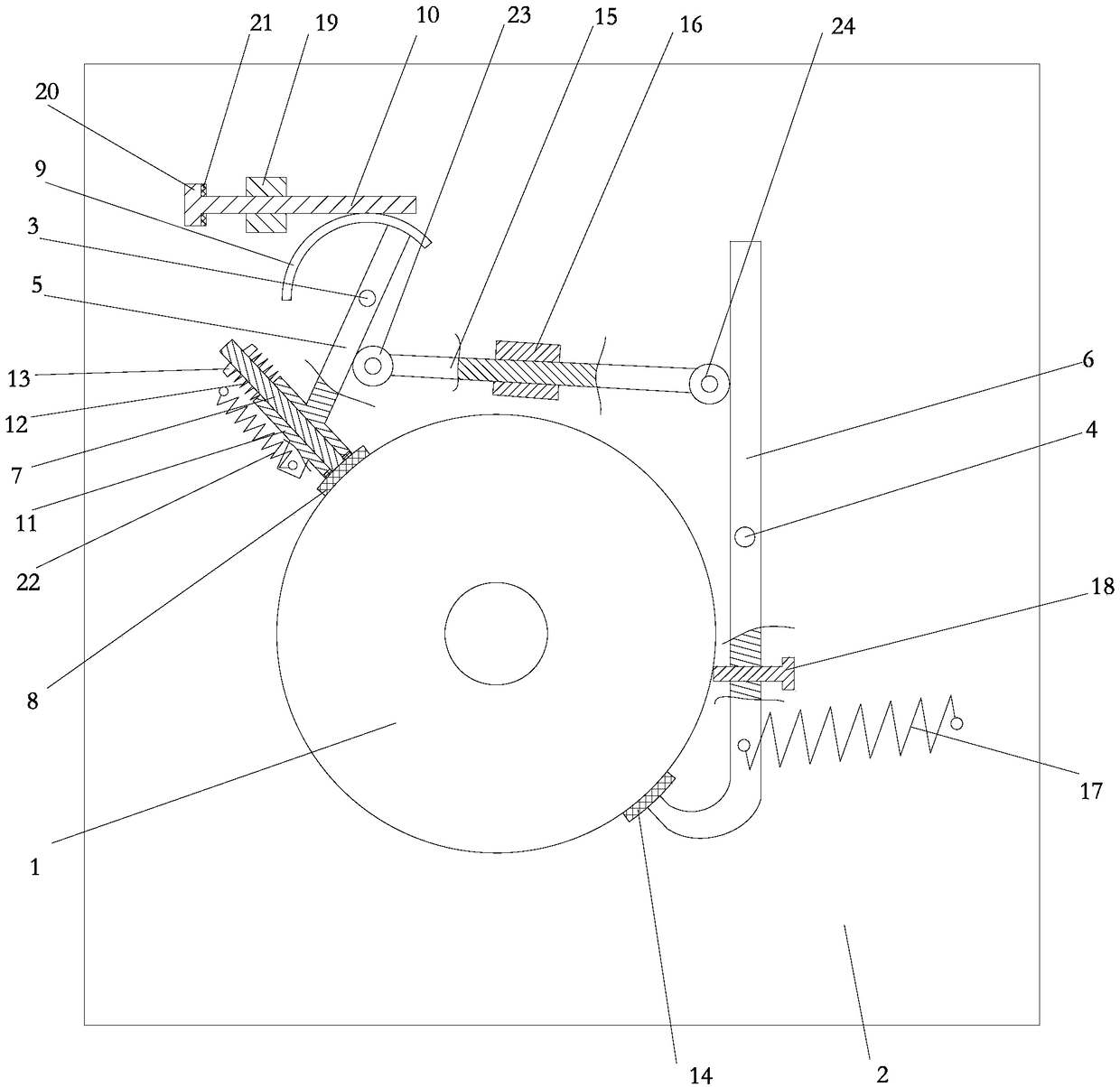
Figure 1 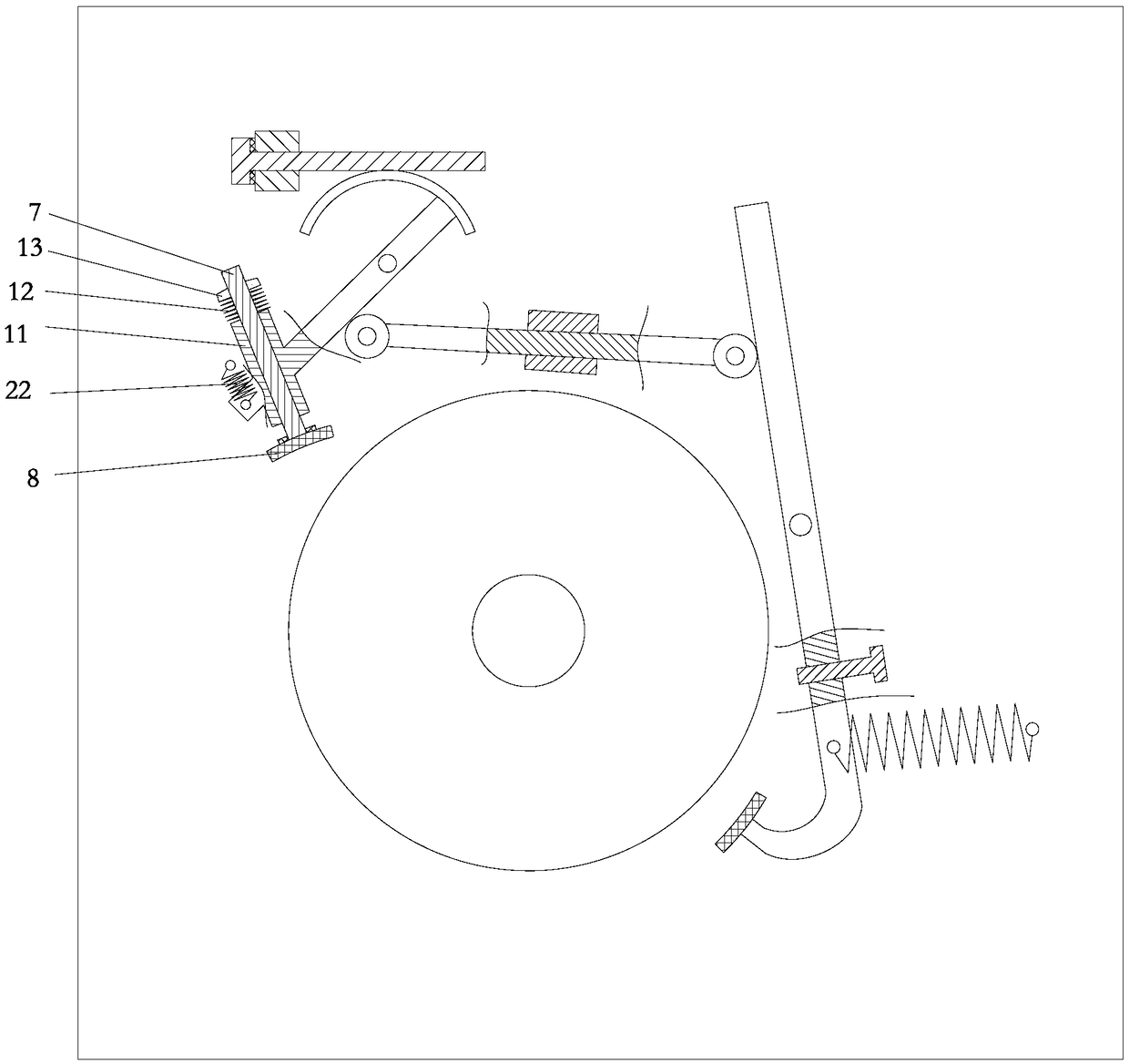
Figure 2
Abstract
Description
technical field
[0001] The invention relates to a device for automatic deceleration of shaft parts. Background technique
[0002] In the process of life and workshop processing, it is often necessary to decelerate some shaft parts. For example, the brakes of bicycles are far away. When it is necessary to brake the front or rear wheels of the bicycle, it is mainly to decelerate the shaft of the front wheel or the shaft of the rear wheel. Currently, disc brakes or suspension brakes are usually used to decelerate the shaft. The ultimate goal is to reduce the rotational speed of the rotating shaft; another example is in machining, the rotating shaft used to drive the tool to rotate needs to be reduced to zero as soon as possible after machining, so as to avoid accidental injury caused by the tool continuing to rotate after machining. There are also a large number of devices in the prior art that are used to lower the rotating shaft of shaft parts, but most of them have the disa...
Examples
Embodiment Construction
[0015] The present invention will be further described below in conjunction with the accompanying drawings and specific embodiments.
[0016] As shown in the figure, the device for automatic deceleration of shaft parts in the present invention includes a base 2 for rotating shaft 1, that is, rotating shaft 1 is rotationally connected to base 2, and base 2 can be installed on an electric motor that drives rotating shaft 1 to rotate. On the tool, the base 2 is rotatably connected to a swing rod 5 and a push rod 6 on the periphery of the rotating shaft 1 through the first hinge point 3 and the second hinge point 4 respectively, and a guide rod 7 is slidably connected to the end of the swing rod 5 close to the outer wall of the rotating shaft 1. The end of the guide rod 7 close to the outer wall of the rotating shaft 1 is provided with a first rubber layer 8 for pressing against or disengaging from the outer wall of the rotating shaft 1 , and the end of the swing rod 5 far away fro...