
Deployable bifurcated rib high-precision reflector
A high-precision, reflective surface technology, applied to antennas, folded antennas, electrical components, etc., can solve the problems of maintaining the accuracy of small flexible antennas, and achieve the effects of avoiding torsional deformation, improving specific stiffness, and reducing structural quality
Patent Information
- Authority / Receiving Office
- CN · China
- Patent Type
- Patents(China)
- Current Assignee / Owner
- Publication Date
- 2020-03-13
Smart Images
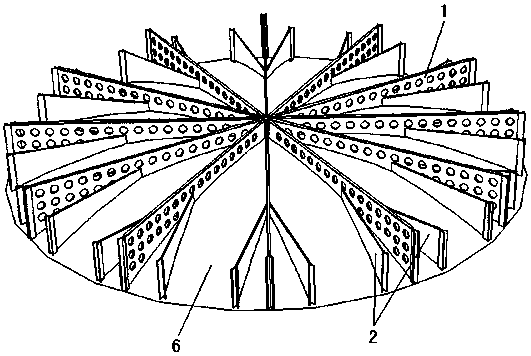
Figure 1 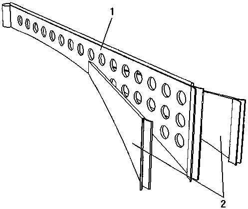
Figure 2 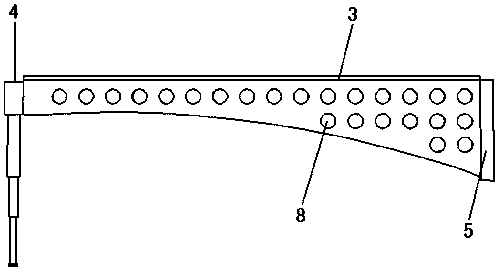
Figure 3
Abstract
Description
technical field
[0001] The invention belongs to the technical field of antennas, and relates to an antenna reflection surface, in particular to a high-precision antenna reflection surface of a deployable bifurcated rib plate. Background technique
[0002] The reflective surface of the rotating parabolic antenna with traditional winding ribs has low out-of-plane bending stiffness of the ribs, which is prone to local buckling and forms out-of-plane wave-like out-of-plane displacement; However, it is sparse at the outer edge of the reflective surface, that is, the distance between two adjacent points on the ideal paraboloid in the latitudinal direction gradually increases, resulting in the middle area not satisfying the ideal paraboloid, and weakening the surface accuracy of the radial radiation rib antenna. Contents of the invention
[0003] The purpose of the present invention is to provide a high-precision reflective surface of a bifurcated rib plate that can be deployed, ...
Examples
specific Embodiment approach 1
[0024] Specific implementation mode one: as Figure 1-4 As shown, the expandable bifurcated rib plate high-precision reflective surface in this embodiment is mainly composed of a central hub 4, a main rib plate 1, an auxiliary rib plate 2, a parabolic reflective surface 6, a positioning pressing plate spring, a pressing belt, The waveguide rod 7 and the feed source are composed of eight parts, among which:
[0025] Main rib 1: In order to reduce the mass of the main rib 1, that is, to increase the specific stiffness per unit mass, several round holes 8 are evenly arranged on the surface of the main rib 1. In order to improve the out-of-plane bending stiffness and torsional stiffness of the main rib 1, the outer edge of the main rib 1 is designed with an open thin shell 5 that is less than pi (pi) / 2 radians, and the open thin shell 5 has an arc less than 90 ° The C-shaped cylindrical shell, after unfolding, looks like a "person". The upper edge of the main rib plate 1 is desi...
specific Embodiment approach 2
[0032] Embodiment 2: The difference between this embodiment and Embodiment 1 is that the secondary floor 2 is bifurcated at 1 / 3 or 1 / 4 of the length direction of the main floor 1 (the bifurcation angle is 25°).
specific Embodiment approach 3
[0033] Specific embodiment 3: The difference between this embodiment and specific embodiments 1 and 2 is that the secondary floor 2 is located at two or 1 / 2, 1 / 3, 1 / 4 of the length direction of the main floor 1. Three forks (fork angle 25°).