
Yarn tension constant compensation device
A compensating device, a technology for yarn tension, applied in textiles and papermaking, knitting, warp knitting, etc., can solve the problems of inability to achieve smooth, stable and continuous operation of equipment, long spring response time, strong yarn jitter, etc. Good shock absorption effect, high product quality, and the effect of reducing production costs
Patent Information
- Authority / Receiving Office
- CN · China
- Patent Type
- Applications(China)
- Current Assignee / Owner
- Publication Date
- 2017-10-24
Smart Images
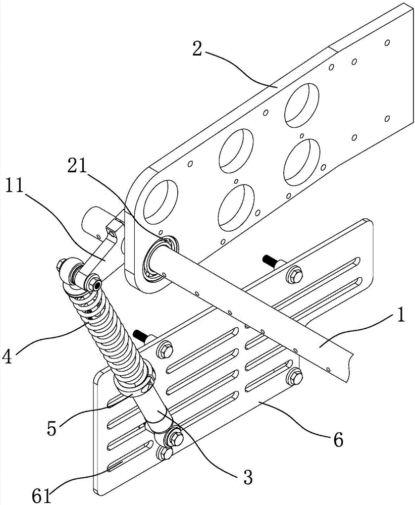
Figure 1 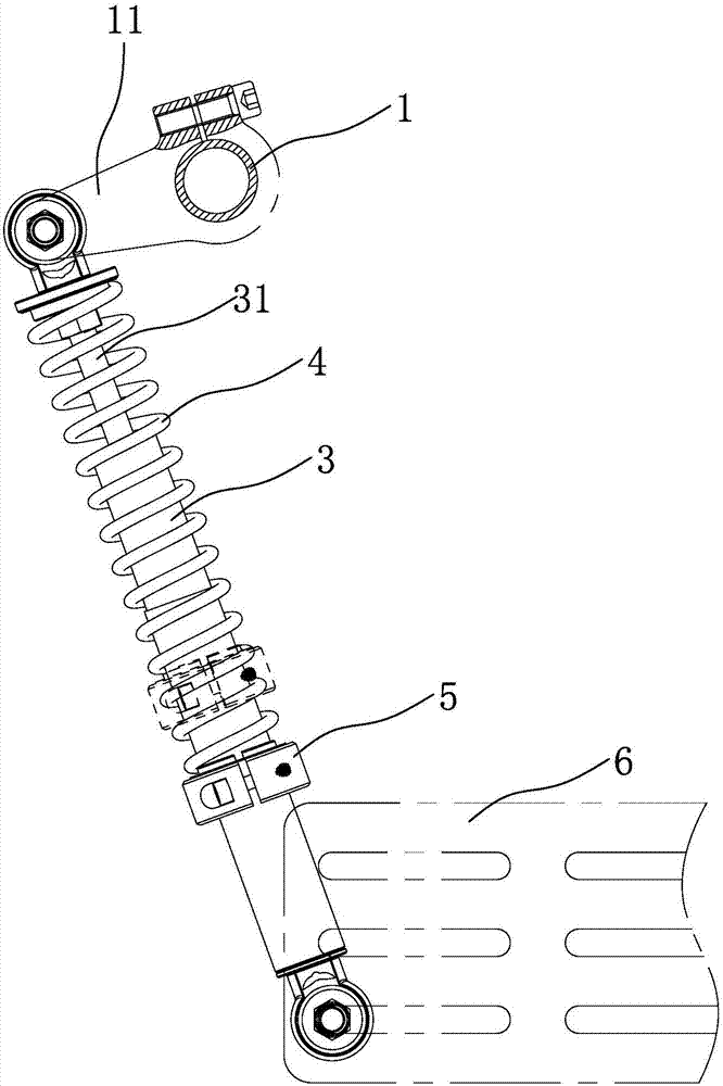
Figure 2 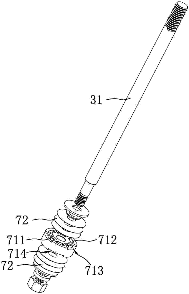
Figure 3
Abstract
Description
technical field
[0001] The invention relates to the technical field of textile equipment, in particular to a yarn tension constant compensation device. Background technique
[0002] Due to the special motion required for knitting and the special requirements for the quality of the cloth surface of the warp knitting machine, the yarn needs to maintain a constant tension so that the equipment can maintain stable operation. In the prior art, a spring is installed on the equipment, one end of the spring is fixed on the frame, and the middle is connected by a chain and a sprocket, and the sprocket is fixed on the yarn guide rod, and the yarn guide rod rotates, driving the sprocket to pull the spring back and forth to expand and contract. Shock absorption, such as the Chinese patent CN102108599B with the date of authorization announcement on May 02, 2012, discloses a warp knitting machine yarn tension control device, the yarn guide rod, tension rod and yarn guide cap supported by ...
Examples
Embodiment
[0016] refer to figure 1 and figure 2 , a kind of yarn tension constant compensating device, comprises frame and six yarn guide rods 1 ( figure 1 Only one is shown as an example), the frame is provided with a support plate 2 with six mounting holes, and each yarn guide rod 1 is installed on the support plate 2 through self-aligning bearings 21;
[0017] Each yarn guide rod 1 is connected with a tension compensation mechanism, and the tension compensation mechanism includes a damping cylinder 3, a spring 4 sleeved on the outer surface of the damping cylinder 3, and a clamp ring 5, and one end of the damping cylinder 3 is fixed on the frame. On a mounting plate 6, the other end is connected to the yarn guide rod 1 through a connecting lever 11, the spring 4 is clamped between the end of one end of the damping cylinder 3 and the clamping ring 5, and the clamping ring 5 is connected to the damping Cylinder 3 threaded connection. In this embodiment, the outer surface of the cyl...