
Hand-hydraulic pipe bender
A pipe bending machine and hydraulic technology, which is applied in the field of hydraulic equipment, can solve the problems that the bending angle cannot be accurately controlled, is not suitable for pipes, and is expensive to process, and achieves accurate angle processing, simple and convenient operation, and reasonable structural design. Effect
Patent Information
- Authority / Receiving Office
- CN · China
- Current Assignee / Owner
- Publication Date
- 2017-11-21
- Estimated Expiration
- Not applicable · inactive patent
Smart Images
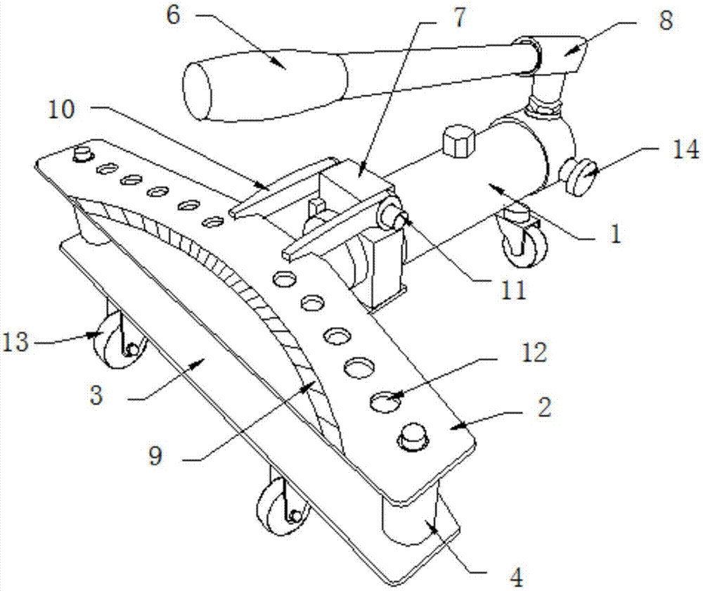
Figure 1 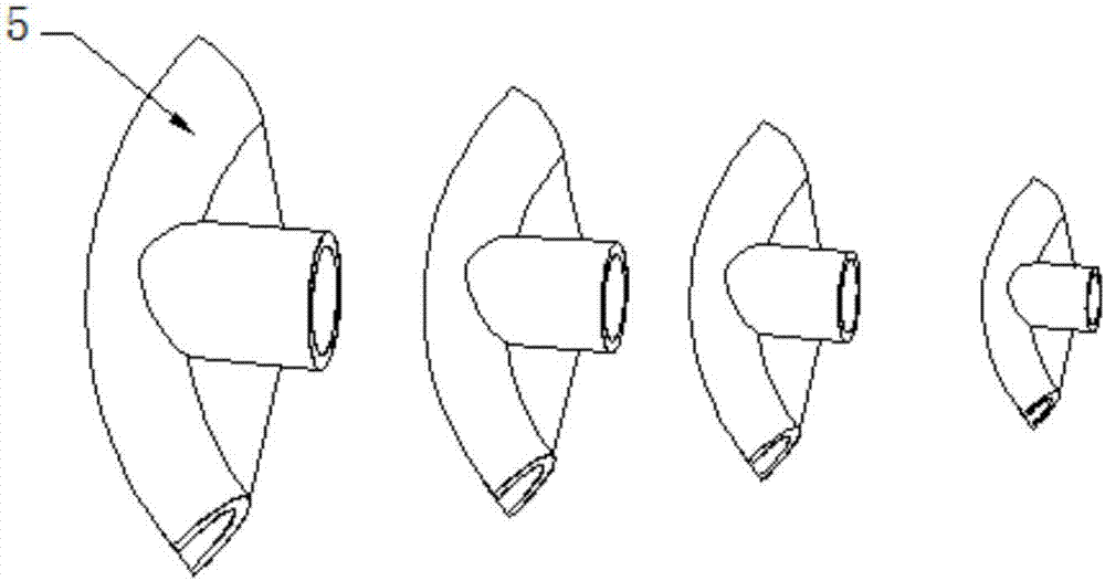
Figure 2
Abstract
Description
technical field
[0001] The invention relates to a manual hydraulic pipe bending machine, which belongs to the field of hydraulic equipment. Background technique
[0002] Pipe benders can be roughly divided into CNC pipe benders, hydraulic pipe benders, etc.; they are mainly used for laying and repairing pipes in power construction, highway and railway construction, boilers, bridges, ships, furniture, decoration, etc.; their defects are metal During the bending process of the pipe, its bending angle cannot be precisely controlled. At the same time, most pipe bending machines are operated automatically or semi-automatically. The structure is too complicated and the processing is expensive, so it is not suitable for processing a small amount of pipes. Contents of the invention
[0003] The technical problem to be solved by the present invention is to overcome the defects of the prior art and provide a manual hydraulic pipe bender.
[0004] In order to solve the problems of t...
Examples
Embodiment
[0018] Such as Figure 1-2 As shown, a manual hydraulic pipe bending machine includes a hydraulic cylinder 1, an upper clamping plate 2, a lower clamping plate 3, a movable limiter 4, a pipe bending die 5 and a handle 6, and one end of the hydraulic cylinder 1 is provided with The upper clamping plate mounting seat 7, the other end of the hydraulic cylinder 1 is provided with a handle mounting base 8, the lower clamping plate 3 is connected with the hydraulic cylinder 1 under one end of the upper clamping plate mounting base 7 through bolts Side connection, the upper surface of the upper clamping plate 2 is provided with an angle ruler 9, and one side of the upper clamping plate 2 is provided with a pair of connecting arms 10, and the connecting arms 10 are provided with a connecting shaft 11, and the connecting arms 10 pass through The connecting shaft 11 is connected with the upper clamp mounting base 7, the movable limiter 4 is set to two, and the two ends of the two movabl...