
The control method to prevent the core pulling of the inner ring of the steel coil when the coiler unloads the coil
A control method and coiler technology, which are applied in the field of automatic control of metallurgical cold rolling, can solve the problem that the gap becomes smaller, and can not completely eliminate the scratches on the inner ring of the coil, the core pulling, the left and right ends of the area and the coil. Problems such as the cylinder gap becoming larger
Patent Information
- Authority / Receiving Office
- CN · China
- Patent Type
- Patents(China)
- Current Assignee / Owner
- Publication Date
- 2019-04-16
Smart Images
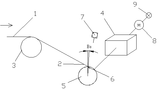
Figure 1 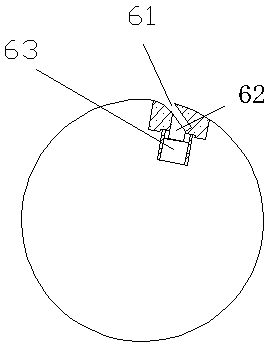
Figure 2 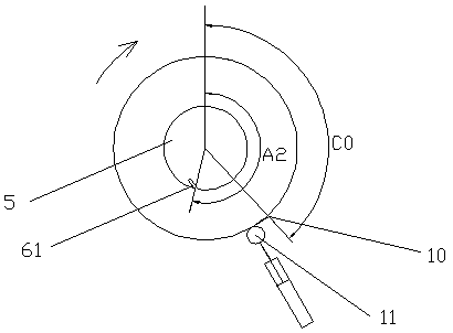
Figure 3
Abstract
Description
Technical field:
[0001] The invention relates to a control method for preventing core-pulling of the inner ring of a steel coil when a coiler unloads coils, and belongs to the technical field of automatic control of metallurgical cold rolling. Background technique:
[0002] see figure 1 , 2 , in the modern cold-rolled pickling production line, due to the thicker strip steel specifications, the reel 5 of the coiler 4 is often provided with a jaw mechanism 6 . In the production process, before the coiler 4 coils the steel strip 1, in order to ensure that the tape head 2 can be smoothly introduced into the jaw 61, the position of the jaw 61 needs to be positioned between the reel 5 and the steering roller through the jaw positioning photoelectric switch 7. The anastomosis positions of the three common tangent lines, that is, the jaws 61 are in the waiting position for insertion. After the tape head 2 is introduced into the jaws 61, the hydraulic cylinder 63 promotes the depr...
Examples
Embodiment Construction
[0086] The specific embodiment of the present invention will be further described below in conjunction with accompanying drawing:
[0087] see figure 1 , 2 Before coiling steel strip 1 in the production line, the jaw mechanism 6 of the drum 5 is positioned at the angle A0 of the common tangent line between the drum 5 and the steering roller 3. After the coiling starts, the tape head 2 is introduced into the jaw 61 and is driven by the hydraulic cylinder. The depressing tongue 62 that 63 drives presses and clamps. Simultaneously, the motor of the coiler 4 drives the reel 5 to rotate clockwise.
[0088] see image 3 , 4 , in order to avoid that the position of the jaw 61 cannot be precisely positioned after the coiling is completed and the belt tail 10 is positioned in the prior art, and the jaw 61 stops at a position such as Figure 4 (a) The area shown in (b) leads to problems such as difficulty in opening the jaw 61 and too small gap with the inner ring of the steel coil...