
Coal mine underground grooving machine
A technology of slotting machine and coal mine, applied in cutting machinery, slitting machinery, propulsion, etc., can solve problems such as hidden safety hazards and low construction efficiency, and achieve the effects of improving efficiency, high operating efficiency, and increasing mechanization rate
Patent Information
- Authority / Receiving Office
- CN · China
- Patent Type
- Applications(China)
- Current Assignee / Owner
- Publication Date
- 2018-01-09
Smart Images
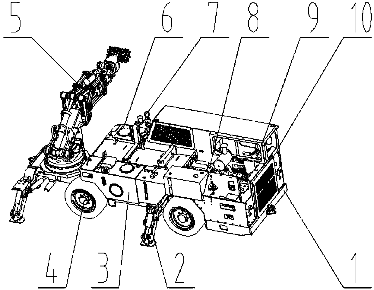
Figure 1 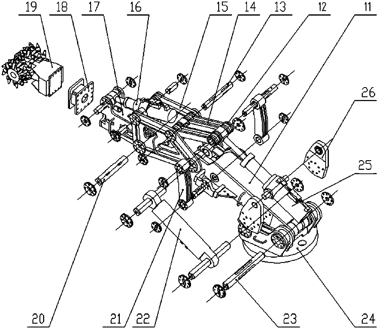
Figure 2 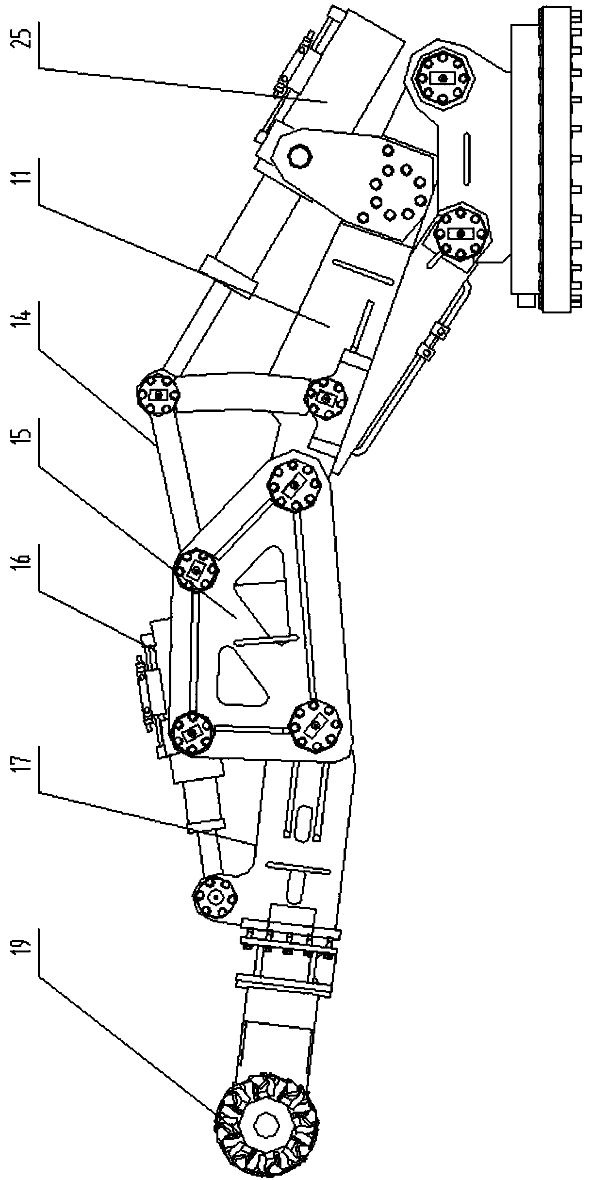
Figure 3
Abstract
Description
technical field
[0001] The invention relates to a coal mine underground equipment, in particular to an underground coal mine slotting machine. Background technique
[0002] In coal mine underground roadway construction operations, after the overall construction work is completed, individual roadways still need to be repaired or slotted partially, such as the installation of air doors and the sealing of the roadway. Grooving operation is carried out with the top plate, and secondary construction is carried out. Originally, this kind of operation was completely dependent on manual work, and many people used simple crushing tools, which resulted in low construction efficiency and great potential safety hazards. Contents of the invention
[0003] The technical problem to be solved by the present invention is to propose a coal mine underground slotting machine with compact structure, flexible joints, large swing range, high reliability and convenient installation and disassemb...
Examples
Embodiment Construction
[0017] An underground slotting machine for coal mines, comprising a frame 1 on which a traveling mechanism 4, a hydraulic oil tank 3, a cab assembly 10, a hydraulic system, an electrical system 7, a pneumatic system 9, a dust removal system 6, and a power Device 8 and slotting device 5, said slotting device 5 is arranged on the rear end of vehicle frame 1, and slotting device 5 comprises cutting head 19 for slotting of underground roadway and base 24 installed on vehicle frame 1 through slewing bearing , the boom 11 is hinged on the base 24 through the hinge shaft I23 arranged horizontally, and the boom drive oil cylinder 22 for driving the boom to swing up and down is arranged between the boom 11 and the base 24; the front end of the boom is passed through the hinge shaft II is hinged with a middle arm 15, and the hinge axis II is set parallel to the hinge axis I; swing arms 21 are respectively installed on the left and right sides of the front part of the boom, and the lower ...