
Slide valve element type balance valve treadmill drive control system
A technology of driving control and balancing valve, which is applied to the training equipment, sports accessories, mechanical equipment, etc. to adjust the cardiovascular system. , low cost, low noise effect
Patent Information
- Authority / Receiving Office
- CN · China
- Patent Type
- Applications(China)
- Current Assignee / Owner
- Publication Date
- 2018-01-19
Smart Images
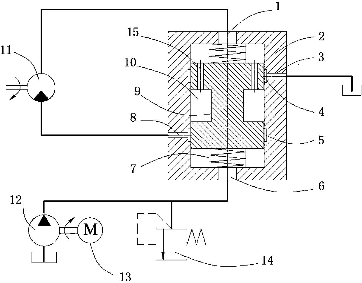
Figure 1
Abstract
Description
technical field
[0001] The invention belongs to the field of fitness equipment and hydraulic control systems, and relates to a sliding valve spool type balance valve treadmill drive control system suitable for commercial or household treadmills. Background technique
[0002] Treadmill is a very popular fitness equipment, fast running or jogging has become a very popular way of fitness. Along with the more and more popular of this kind of fitness mode, also more and more higher to the performance requirement of treadmill itself. As far as user experience is concerned, apart from various human-machine communication, physical condition monitoring, user interface and other additional functions, the most important indicator to measure the performance of the treadmill is the speed control performance of the treadmill, especially the speed control in the work project. accuracy and stability. Due to the working characteristics of the treadmill, the load generated by the running ac...
Examples
Embodiment Construction
[0024] The above and other technical features and advantages of the present invention are clearly and completely described below in conjunction with the accompanying drawings. Apparently, the described embodiments are only some of the embodiments of the present invention, rather than all of them.
[0025] The present invention will be further described below in conjunction with the accompanying drawings.
[0026] Such as figure 1 As shown, the slide valve spool type balance valve treadmill drive control system provided by the present embodiment mainly consists of a DC brushless motor 13, a miniature hydraulic pump 12, a hydraulic motor 11, a balance valve body 2, and a balance valve spool 9 ( That is, the piston), the end spring 7, the safety valve 14, and the connecting oil passage, including the oil return port 1, the oil inlet 6, the upper oil passage 3, the upper sinking groove 4, the lower oil passage 8, and the sinking cutting groove 5 , Intermediate cavity 10, piston o...