
Liquid crystal panel drive circuit, liquid crystal panel, and liquid crystal panel drive method
A liquid crystal panel and drive circuit technology, applied in the electronic field, can solve the problem that the timing controller cannot be reset, and achieve the effect of solving the problem of not being able to reset
Patent Information
- Authority / Receiving Office
- CN · China
- Patent Type
- Patents(China)
- Current Assignee / Owner
- Publication Date
- 2020-06-30
Smart Images
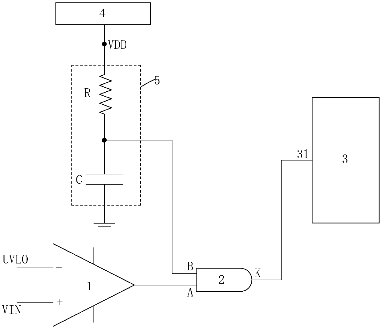
Figure 1 
Figure 2
Abstract
Description
technical field
[0001] The invention relates to the field of electronic technology, in particular to a liquid crystal panel drive circuit, a liquid crystal panel and a liquid crystal panel drive method. Background technique
[0002] Liquid Crystal Display (LCD) has many advantages such as thin body, power saving, and no radiation, and has been widely used, such as: LCD TV, smart phone, digital camera, tablet computer, computer screen, or notebook computer Screens, etc., dominate the field of flat panel displays.
[0003] The liquid crystal panel is mainly composed of a thin film transistor array substrate (Thin Film Transistor Array Substrate, TFT Array Substrate), a color filter substrate (Color Filter, CF), and a liquid crystal layer (Liquid Crystal Layer) arranged between the two substrates. Its working principle is that the driving circuit provides the driving voltage and applies the driving voltage to the two substrates to control the rotation of the liquid crystal mol...
Examples
Embodiment Construction
[0038] In order to further illustrate the technical means adopted by the present invention and its effects, the following describes in detail in conjunction with preferred embodiments of the present invention and accompanying drawings.
[0039] see figure 1 , the present invention firstly provides a liquid crystal panel drive circuit, including a comparator 1, an AND gate 2, a timing controller 3, an integrated power management module 4 and an RC circuit 5.
[0040] The RC circuit 5 includes a resistor R and a capacitor C connected in series; one end of the resistor R is connected to the power supply voltage VDD output by the power management integrated module 4, and the other end is electrically connected to the first plate of the capacitor C; The second plate of capacitor C is grounded.
[0041] The positive input terminal of the comparator 1 is connected to the external input voltage VIN, the negative input terminal is connected to the low-voltage turn-off voltage UVLO of ...