
Method for producing a tapered roller assembly, tapered roller assembly and tapered roller bearing
A tapered roller bearing, tapered roller technology, applied in the direction of roller bearings, shafts and bearings, rolling contact bearings, etc., can solve problems such as cracks and weakening of small flanges
Patent Information
- Authority / Receiving Office
- CN · China
- Patent Type
- Applications(China)
- Current Assignee / Owner
- Publication Date
- 2018-03-27
- Estimated Expiration
- Not applicable · inactive patent
Smart Images
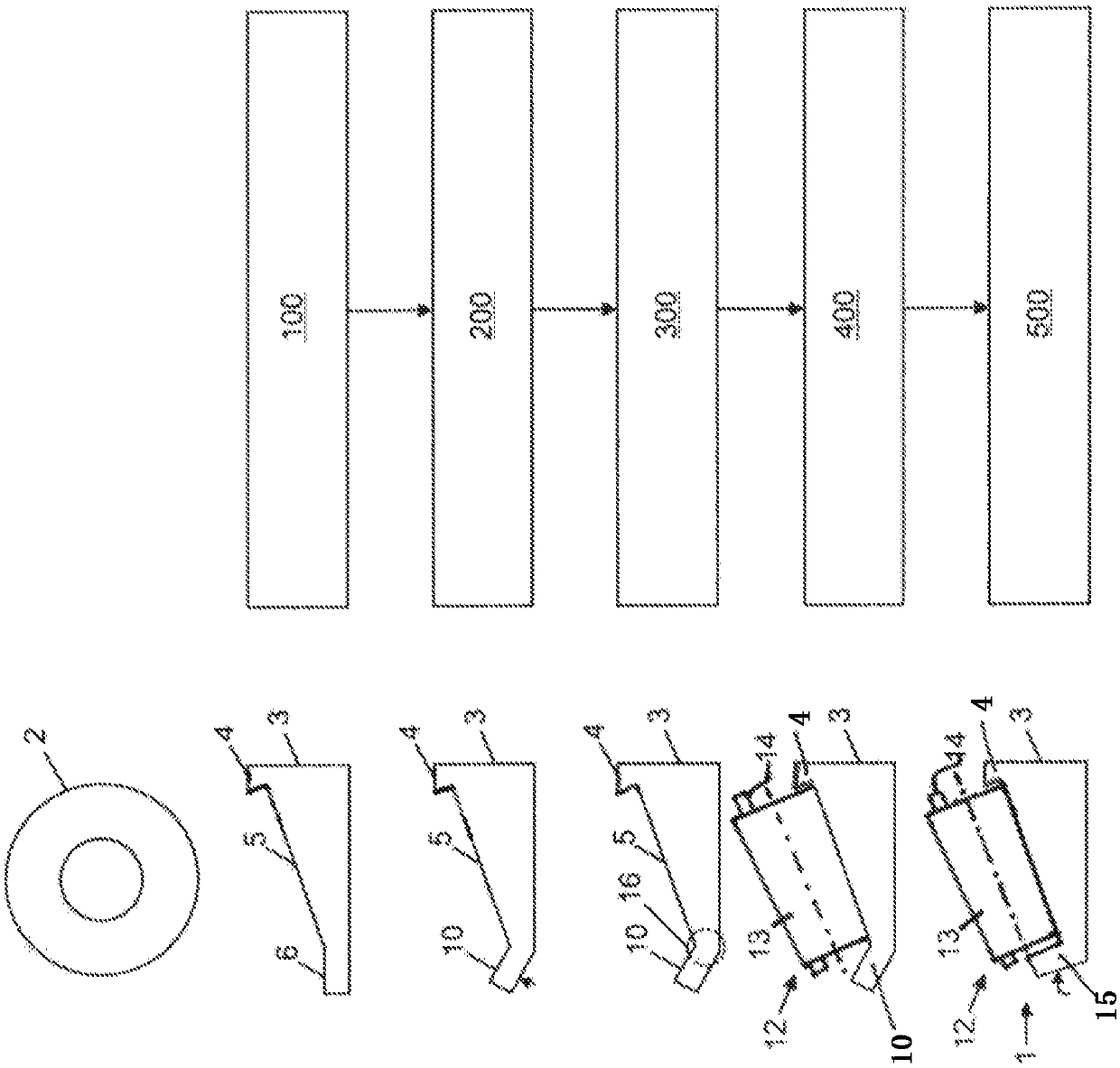
Figure 1 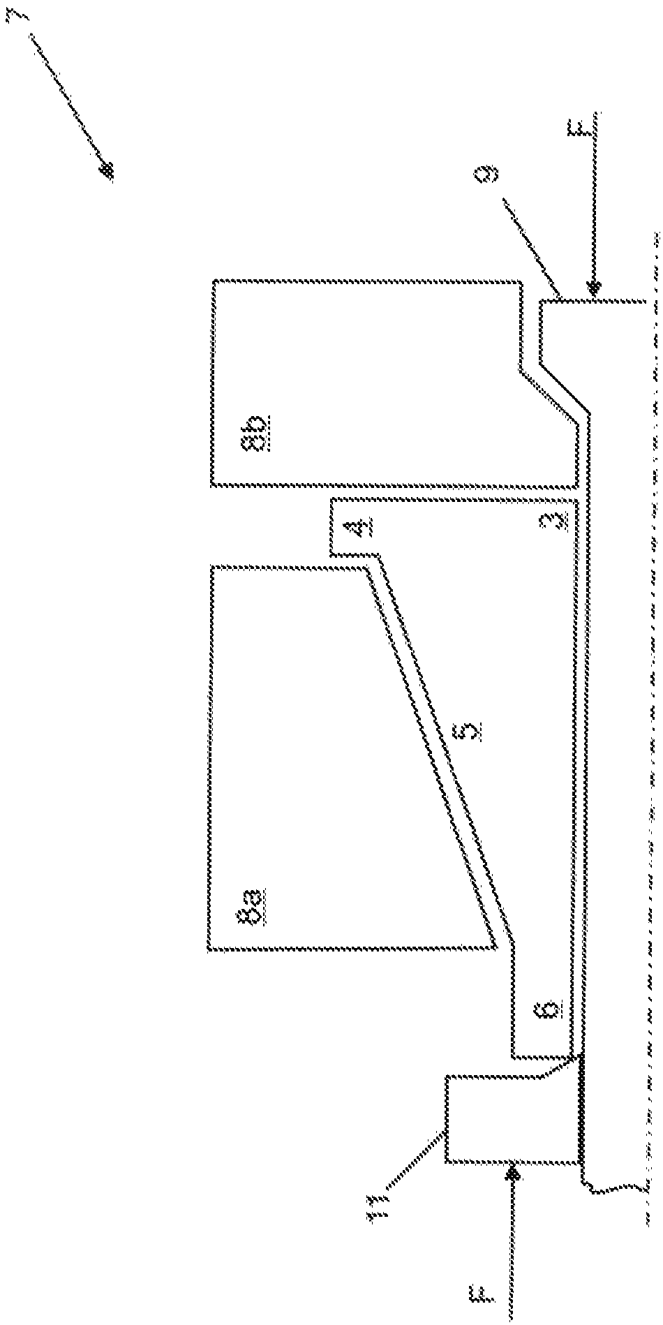
Figure 2 
Figure 3
Abstract
Description
technical field
[0001] The invention relates to a method for manufacturing a tapered roller assembly, wherein the method comprises the steps of: providing an inner ring, wherein the inner ring has a beaded fit edge; fitting a roller and cage assembly to the inner ring , wherein the roller and cage assembly is fitted onto the inner ring through the hemming assembly edge; and the hemming assembly edge is turned into a hemming edge, wherein the hemming edge is used as a retaining edge to hold the roller and retain shelf components. In addition, the present invention also relates to a tapered roller assembly manufactured by the method, and to a tapered roller bearing formed using the tapered roller assembly. Background technique
[0002] Tapered roller bearings in many configurations have an inner ring, an outer ring and a plurality of tapered rollers arranged rolling between the inner ring and the outer ring. These tapered rollers are often guided in cages. The production of...
Examples
Embodiment Construction
[0039] figure 1 On the right is shown a flow chart with a number of steps for producing the tapered roller component set 1 . On the left, a half-sectional view of an initial or intermediate product for producing the tapered roller component assembly 1 is schematically shown.
[0040] By way of example, the method can start from a ring disk 2 produced from a preferably hardenable steel. The annular disk 2 is designed as a flat disk body and can be separated, for example, from a disk blank. In step 100, which is designed as a reforming phase, the annular disc 2 is reformed by cold extrusion into an inner ring 3, wherein the inner ring 3 has a fixed edge 4, a conically extending raceway 5 and an axially extending Border area 6. The edge region 6 is formed as a hollow cylindrical end section of the inner ring 3 .
[0041] For example, the inner ring 3 can be produced in the reforming device 7 in the state after step 100, as it was in figure 2 shown schematically in half-sect...