

Incandescent lamp fitting for fishery farm
A technology for farms and incandescent lamps, applied in the field of lighting equipment, can solve the problems of inconvenient installation and maintenance of lamps, difficult lighting angles, high humidity of lamps, etc., and achieve the effects of facilitating maintenance, reducing humidity, and reducing the probability of short circuit
Patent Information
- Authority / Receiving Office
- CN · China
- Patent Type
- Applications(China)
- Current Assignee / Owner
- Publication Date
- 2018-06-29
- Estimated Expiration
- Not applicable · inactive patent
Smart Images
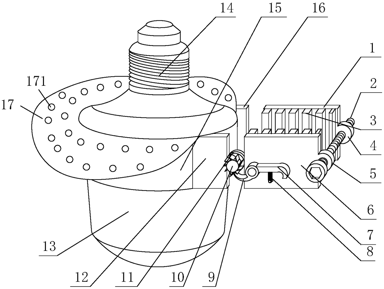
Figure 1 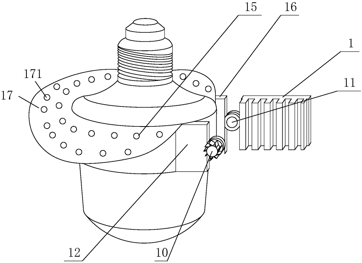
Figure 2 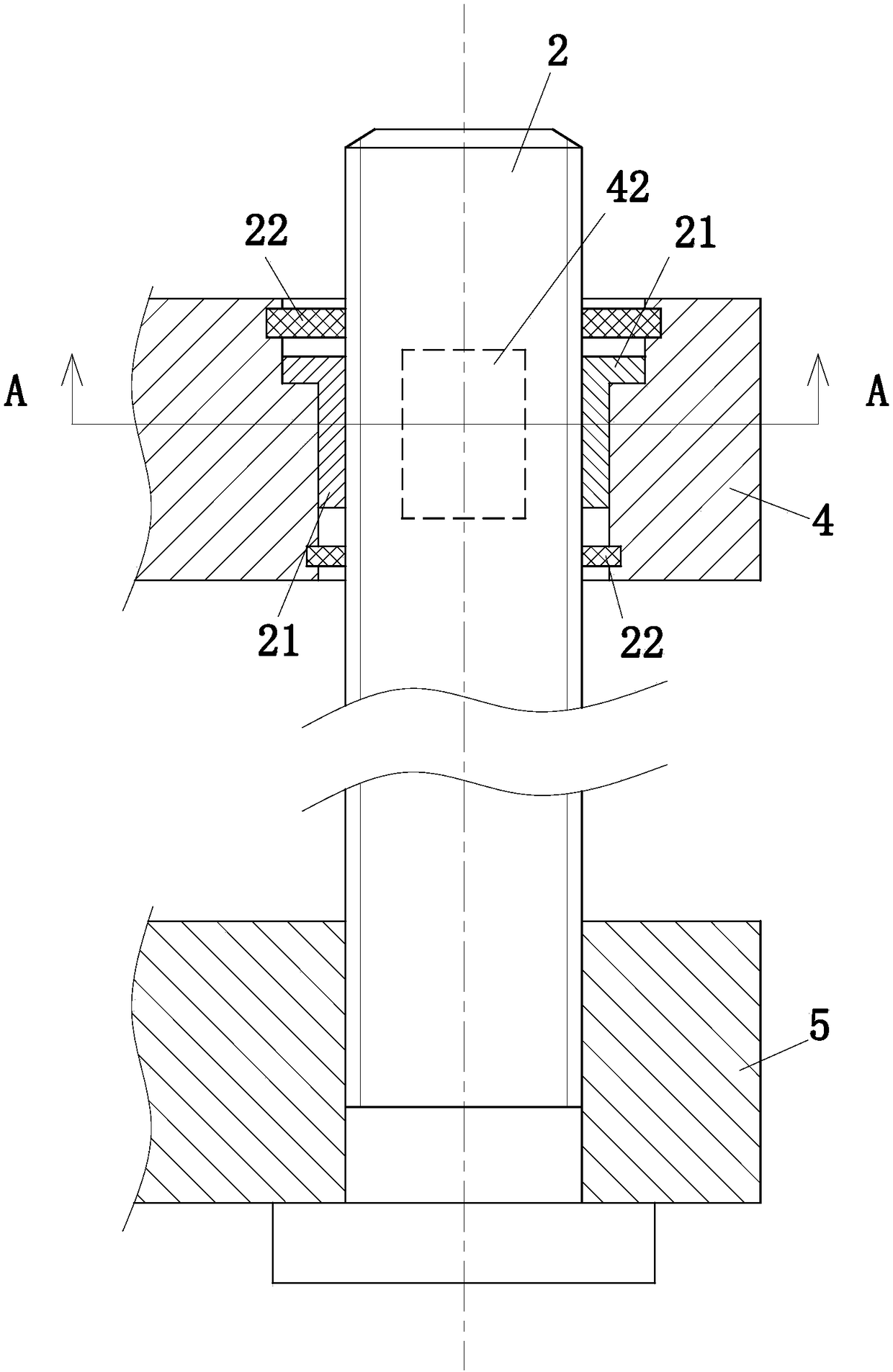
Figure 3
Abstract
Description
technical field
[0001] The invention relates to a lamp, in particular to an incandescent lamp for fish farms, and belongs to the technical field of lighting equipment application. Background technique
[0002] Aquaculture fishery, also known as aquaculture, refers to the cultivation of fish or various seafood in artificially opened fish farms on the shore for consumption. In the existing small and medium-sized farms, a row of lamps for lighting will be set on the shore, which is convenient for farmers to observe the farm and feed fish at night.
[0003] Most of the existing lamps used in fish farms are hung high to improve the vision of lighting, but most of the existing lamps used in fish farms have the following deficiencies:
[0004] (1) When installing the lamps, the lighting angle of the lamps is not easy to adjust. In order to improve the stability of the lamps, most of the existing lamps are directly fixed by bolts, and this method is often not convenient for adjusti...
Examples
Embodiment Construction
[0019] The following will clearly and completely describe the technical solutions in the embodiments of the present invention with reference to the accompanying drawings in the embodiments of the present invention. Obviously, the described embodiments are only some, not all, embodiments of the present invention. Based on the embodiments of the present invention, all other embodiments obtained by persons of ordinary skill in the art without making creative efforts belong to the protection scope of the present invention.
[0020] Such as Figure 1 to Figure 4 As shown, an incandescent light fixture for fish farms according to the present invention includes a lampshade 15, a lamp cap 14 is provided at the top of the lampshade 15, an incandescent bulb 13 is provided at the bottom of the lampshade 15, and the One side of the lampshade 15 is provided with a second fixed block 12; one side of the second fixed block 12 is rotatably connected to a rotating shaft 11, and one end of the ...