
Power maintenance system
It is a technology for electric power maintenance and casing, which is applied in the direction of electrical components, overhead lines/cable equipment, switchgear, etc. It can solve the problems of wasting human resources, inconvenient management, and increasing the amount of manual labor, and achieve resource saving and excellent dehumidification function. Effect
Patent Information
- Authority / Receiving Office
- CN · China
- Patent Type
- Patents(China)
- Current Assignee / Owner
- Publication Date
- 2020-05-05
- Estimated Expiration
- Not applicable · inactive patent
Smart Images
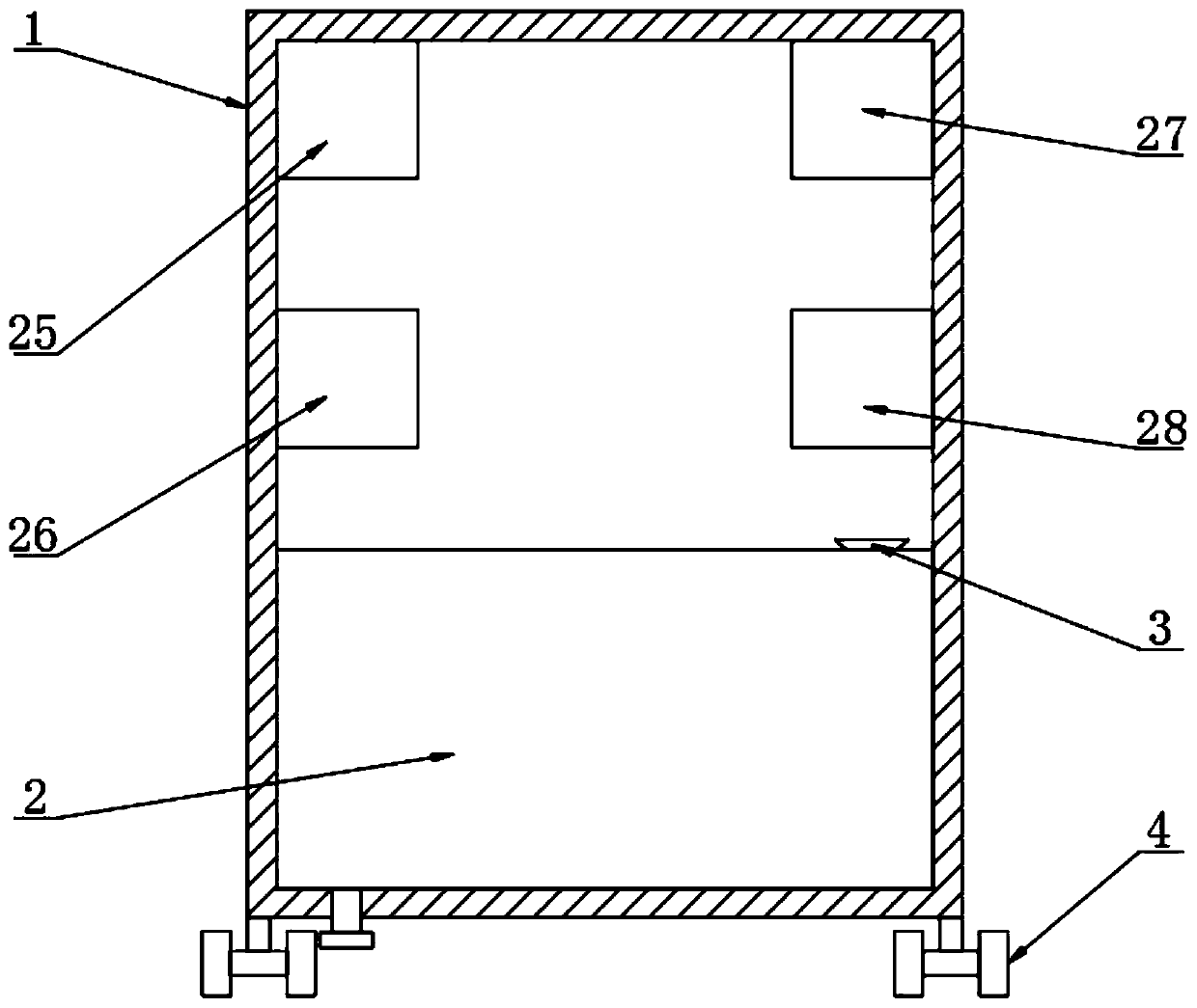
Figure 1 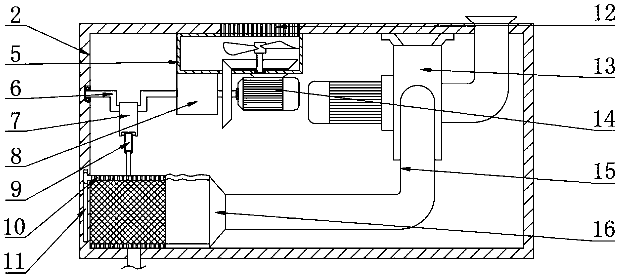
Figure 2 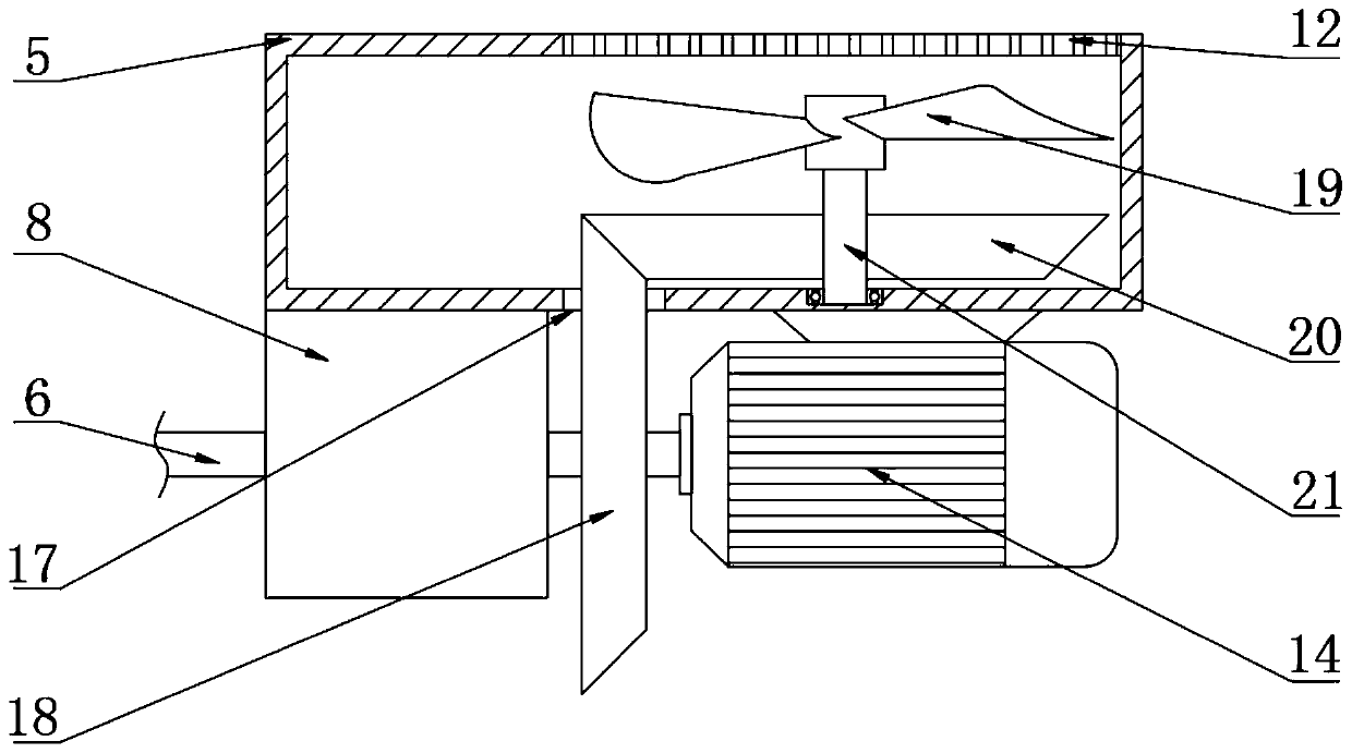
Figure 3
Abstract
Description
Technical field
[0001] The present invention relates to the technical field of electric power maintenance equipment, in particular to a power maintenance system. Background technique
[0002] With the rapid development of the power system, the continuous expansion of the scale of the system, and the rapid growth of the number of equipment in the system, the traditional "one size fits all" regular maintenance mode does not evaluate the status of power transmission and transformation equipment. Because the maintenance time is fixed, there is maintenance Disadvantages of insufficient and over-maintenance. At present, when a power failure occurs, it is impossible to monitor all equipment in real time. After the repair work is completed, it is impossible to notify in time. This often leads to repeated dispatch of maintenance personnel to repair the same equipment, which greatly wastes human resources and increases the amount of labor. , It is not easy to manage. Summary of the invent...
Examples
Embodiment Construction
[0021] The technical solutions in the embodiments of the present invention will be clearly and completely described below in conjunction with the accompanying drawings in the embodiments of the present invention. Obviously, the described embodiments are only a part of the embodiments of the present invention, rather than all the embodiments. Based on the embodiments of the present invention, all other embodiments obtained by those of ordinary skill in the art without creative work shall fall within the protection scope of the present invention.
[0022] See Figure 1-5 , The present invention provides a technical solution: an electric power maintenance system, including a box body 1, a dehumidification housing 2, an air inlet pipe 3, a roller 4, a heat dissipation housing 5, a concave shaft 6, a first connecting rod 7, and a reducer 8. , The second connecting rod 9, the net plate 10, the sliding groove 11, the heat dissipation hole 12, the induced draft fan 13, the motor 14, the ...