
Limiting structure used for inner part of main body pipeline transportation device of tube push bench
A technology of limit structure and transportation device, which is used in pipeline laying and maintenance, pipes/pipe joints/fittings, machinery and equipment, etc. It can solve the main pipelines that cannot adapt to different sizes, and the main pipelines are prone to rolling and falling off safety accidents. and other problems, to achieve the effect of not easy to shake and fall off, reduce friction, and good stability.
Patent Information
- Authority / Receiving Office
- CN · China
- Current Assignee / Owner
- Publication Date
- 2019-01-11
Smart Images
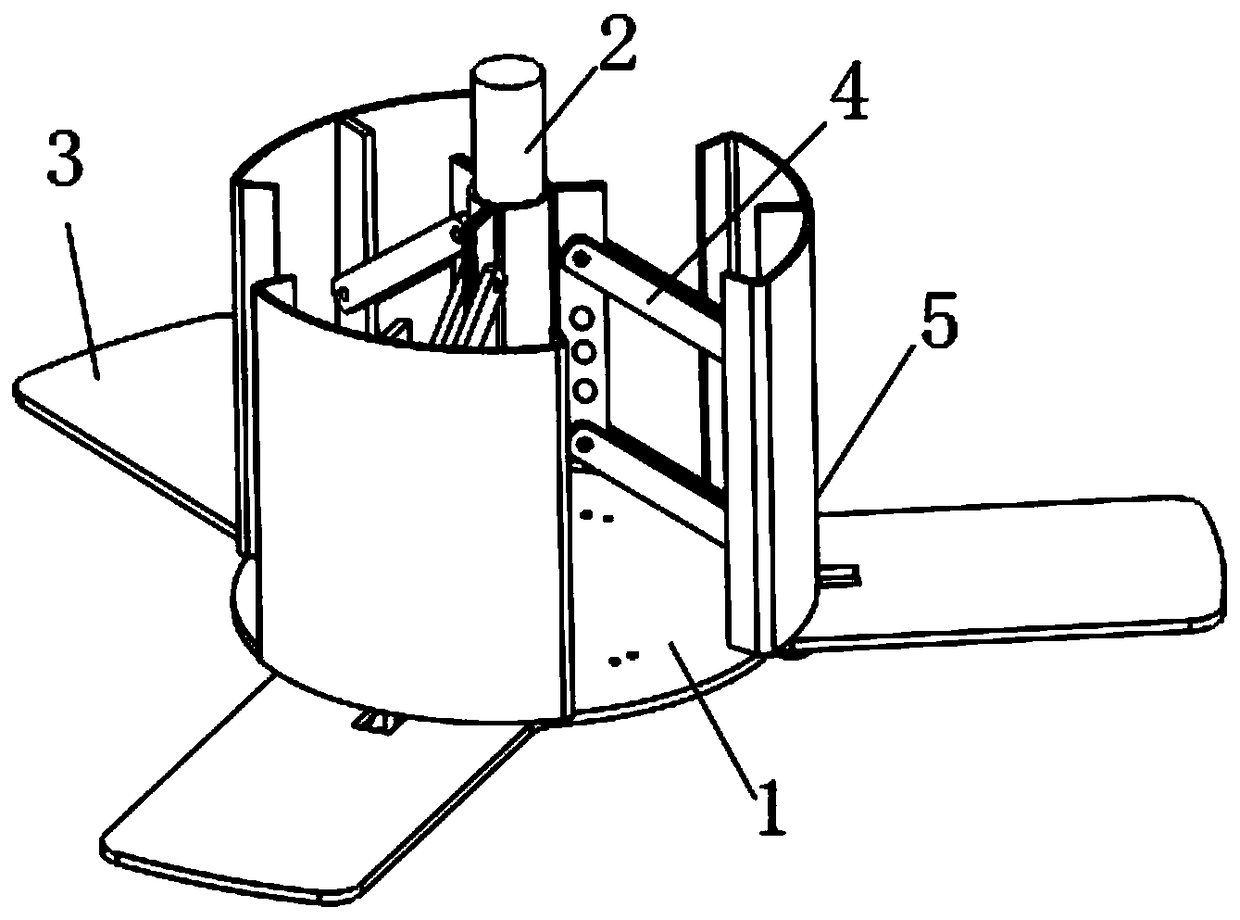
Figure 1 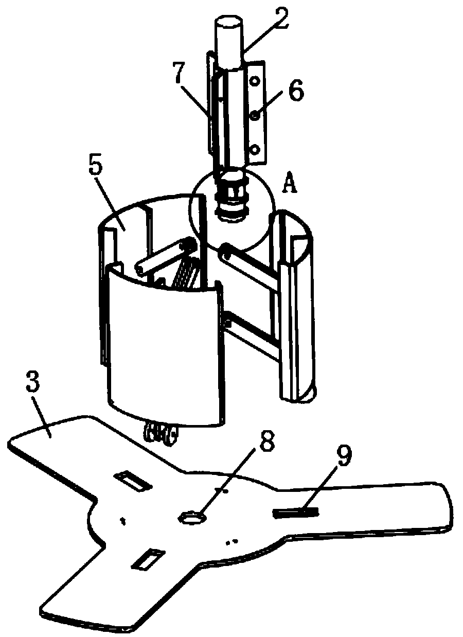
Figure 2 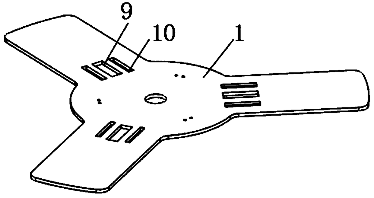
Figure 3
Abstract
Description
technical field
[0001] The invention relates to a position-limiting structure, in particular to a position-limiting structure used inside a pipeline transportation device of a main body of a pipe jacking machine. Background technique
[0002] The pipe jacking machine is a kind of construction machinery specially designed for rock tunnels. It is suitable for various weathered rock soil conditions, and has been more and more widely used in rock tunnel projects such as railways, electric power, water conservancy, coal, mining, transportation, urban underground engineering machines, and subways. Pipe jacking machine is an important equipment for rock tunnel construction. It is mainly used for cutting rock, breaking rock and transporting the broken rock to complete the construction of rock tunnel. The main devices inside the pipe jacking machine are installed inside the hollow main pipeline, and the main pipeline often requires specific devices for transportation.
[0003] Howe...
Examples
Embodiment Construction
[0031] The technical solutions of the present invention will be clearly and completely described below in conjunction with the embodiments. Apparently, the described embodiments are only some of the embodiments of the present invention, not all of them. Based on the embodiments of the present invention, all other embodiments obtained by persons of ordinary skill in the art without creative efforts fall within the protection scope of the present invention.
[0032] see Figure 1-7 As shown, a limit structure for the interior of the pipeline transportation device of the main body of the pipe jacking machine, including a circular chassis 1, a connecting plate 3, a vertical rod 2 and a side plate 5, three sets of connecting plates 3 are evenly connected around the chassis 1, and the connecting The middle part of the plate 3 is provided with a through groove 9 along the length direction, the bottom of the connecting plate 3 is provided with sliding grooves 10 on both sides of the t...