
Automatic adjusting device for built-in volume ratio of fuel cell air compressor
An air compressor and fuel cell technology, applied in the field of air compressors, can solve problems affecting the efficiency of fuel cell systems, waste of power consumption, and reduce compressor efficiency, so as to achieve high applicability, reduce energy consumption, and improve compressor efficiency Effect
Patent Information
- Authority / Receiving Office
- CN · China
- Patent Type
- Applications(China)
- Current Assignee / Owner
- Publication Date
- 2019-06-07
Smart Images
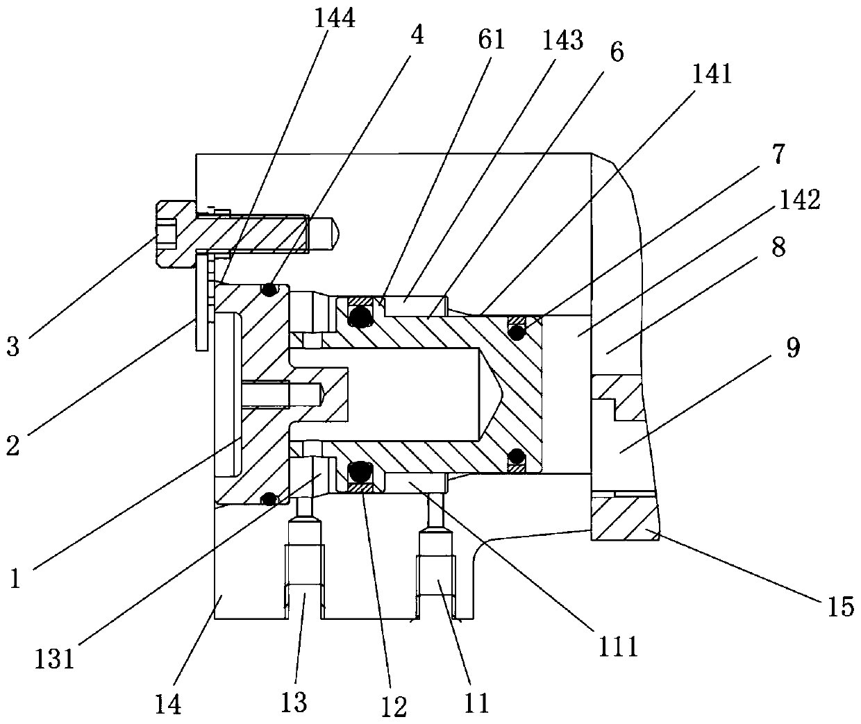
Figure 1 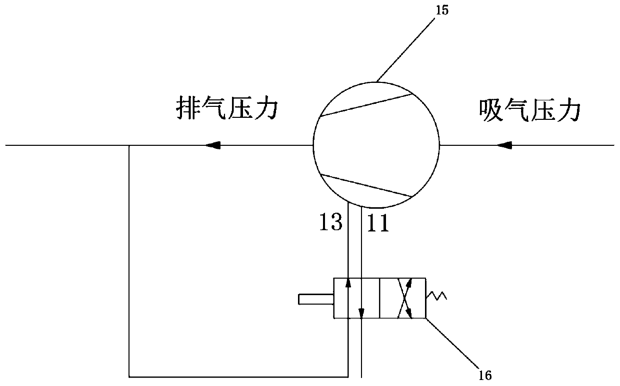
Figure 2 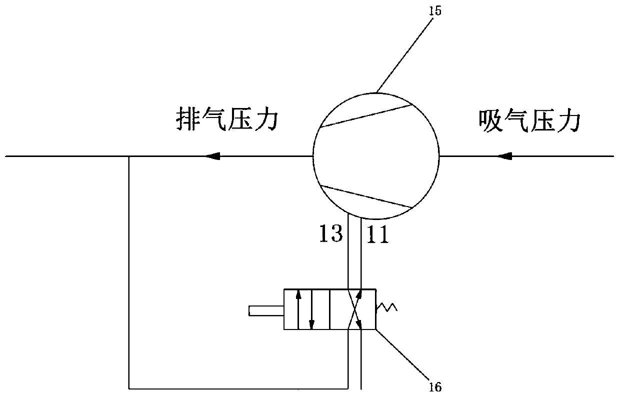
Figure 3
Abstract
Description
Technical field
[0001] The present invention relates to the technical field of air compressors, and in particular to an automatic adjustment device for the built-in volume ratio of an air compressor for a fuel cell. Background technique
[0002] With the increasingly prominent problems of energy scarcity and environmental damage, fuel cell technology has attracted more and more attention.
[0003] The air compressor is an important component of the fuel cell cathode air supply system for vehicles. By pressurizing the air entering the stack, the power density and efficiency of the fuel cell can be improved, and the size of the fuel cell system can be reduced. However, the parasitic power consumption of the air compressor is large, accounting for about 80% of the auxiliary power consumption of the fuel cell system, and its performance directly affects the efficiency, compactness and water balance of the fuel cell system. Therefore, all countries in the world attach great importance ...
Examples
Embodiment
[0047] An automatic adjustment device for the built-in volume ratio of an air compressor for fuel cells, such as figure 1 , figure 2 , image 3 As shown, the exhaust housing 14 is provided on the air compressor; the air compressor is a screw compressor; and the exhaust housing 14 is provided with a mounting through hole 141, and the mounting through hole 141 connects the air compressor The exhaust cavity 8 on the rotor housing 15 is in communication with the bypass air cavity 9; the installation through hole 141 is provided with a capacity plunger 6, when the capacity plunger 6 is attached to the rotor housing 15, exhaust The cavity 8 and the bypass air cavity 9 are not connected. When the volume plunger 6 is separated from the rotor housing 15, the exhaust cavity 8 and the bypass air cavity 9 are connected; in order to ensure the sealing of the volume plunger 6 and the inner wall of the installation through hole 141 The outer wall of the displacement plunger 6 is provided wit...