
T-junction waveguide duplexer
A technology of duplexer and waveguide, applied in the field of microwave passive devices, can solve the problem of large working frequency band span, etc., and achieve the effects of improving electrical performance index, simple structure and easy fabrication
Patent Information
- Authority / Receiving Office
- CN · China
- Patent Type
- Applications(China)
- Current Assignee / Owner
- Publication Date
- 2019-08-16
- Estimated Expiration
- Not applicable · inactive patent
Smart Images
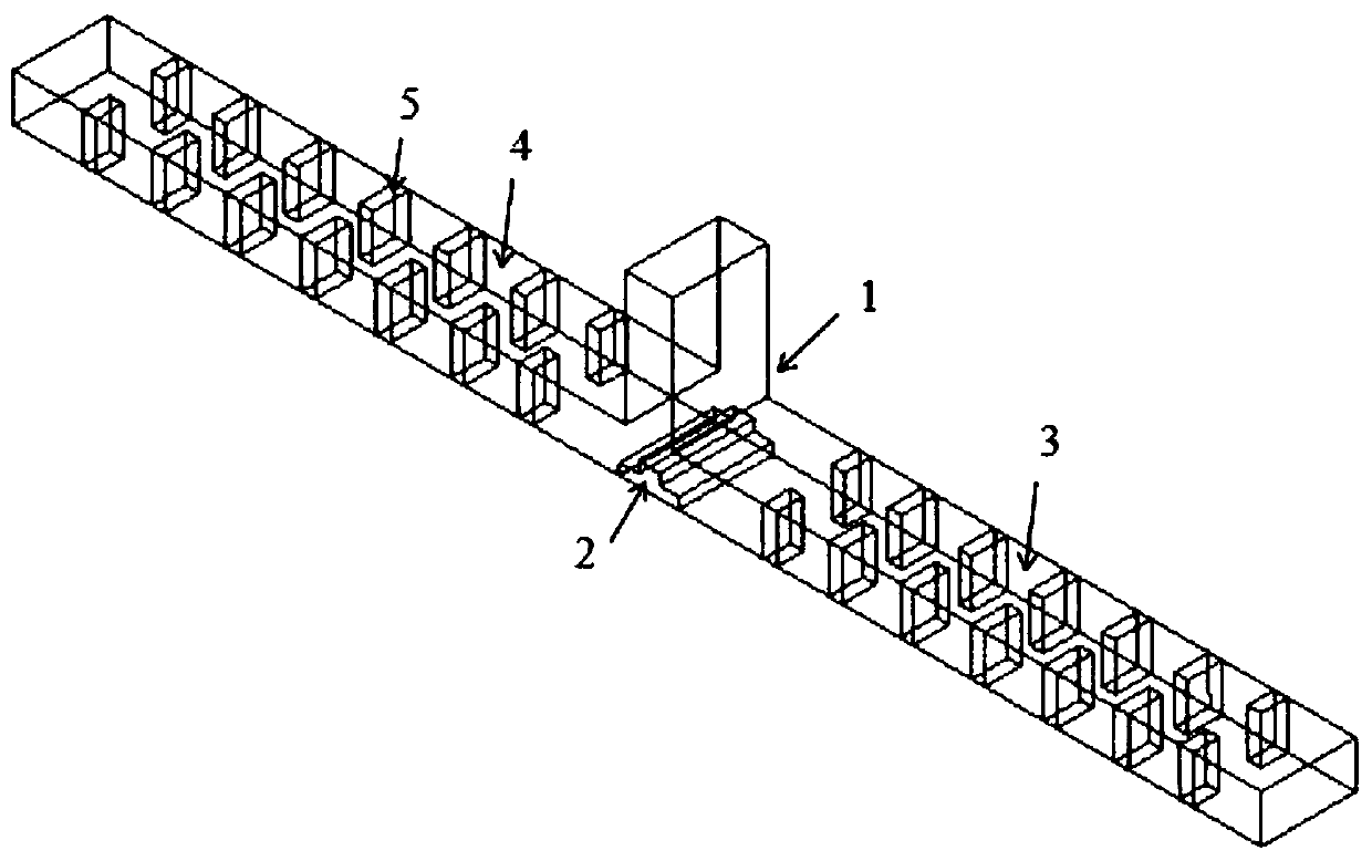
Figure 1 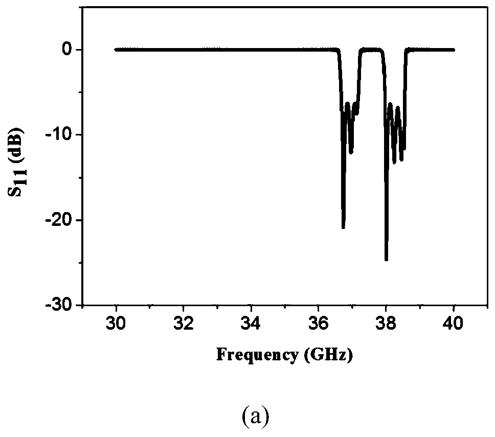
Figure 2 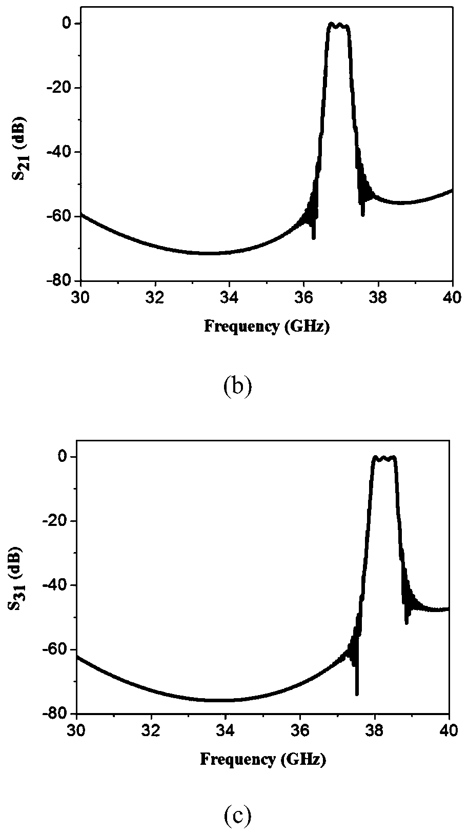
Figure 3
Abstract
Description
Technical field
[0001] The invention relates to a microwave passive device, in particular to a T-junction waveguide duplexer. Background technique
[0002] The duplexer is a microwave passive device, which can realize the separation of receiving and sending signals, and is mainly used to connect the antenna and the transceiver. In modern communication technology, the performance of the duplexer plays a vital role in the entire system. The application of duplexers in measurement and control, precision guidance and military electronic countermeasures is also becoming more and more extensive. The traditional waveguide duplexer is connected to two filters with a circulator, and the two working frequency bands have a large span. Summary of the invention
[0003] Objective of the invention: The objective of the present invention is to provide a T-junction waveguide duplexer to solve the problem of large span of the existing working frequency band.
[0004] Technical solution: The T-jun...
Examples
Embodiment Construction
[0012] The present invention will be further described below in conjunction with the drawings.
[0013] Such as Figure 1-2 As shown, the T-shaped junction waveguide duplexer includes an ET-shaped power divider 1. The output ends of the ET-shaped power divider 1 are respectively connected to a first filter 3 and a second filter 4 with different passbands, and the ET-shaped power divider The common working end of the device 1 is provided with a second step tuning protrusion 2. Metal diaphragms 5 are arranged at intervals in the filter. The metal diaphragm 5 is arranged symmetrically in the filter in two rows. Among them, the tuning bump (2) is a second-stage step bump, the first-stage bump has a width of 3.5-5mm mm and a height of 0.5-1mm, and the second-stage bump has a width of 1-2mm and a height of 0.5-1mm . The length of the filter is 43-46mm, and the thickness of the metal diaphragm (5) is 0.5-1.5mm. The metal diaphragm acts as an equivalent inductance in the filter, com...