
Cyclone melting furnace and using method thereof
A melting furnace and cyclone technology, applied in the application field of cyclone melting furnace, can solve the problems of wear of refractory material, high airflow speed and high strength of cyclone furnace, and achieve the effect of reducing direct scouring, strengthening reaction intensity and increasing flow field distribution
Patent Information
- Authority / Receiving Office
- CN · China
- Current Assignee / Owner
- Publication Date
- 2019-11-01
- Estimated Expiration
- Not applicable · inactive patent
Smart Images
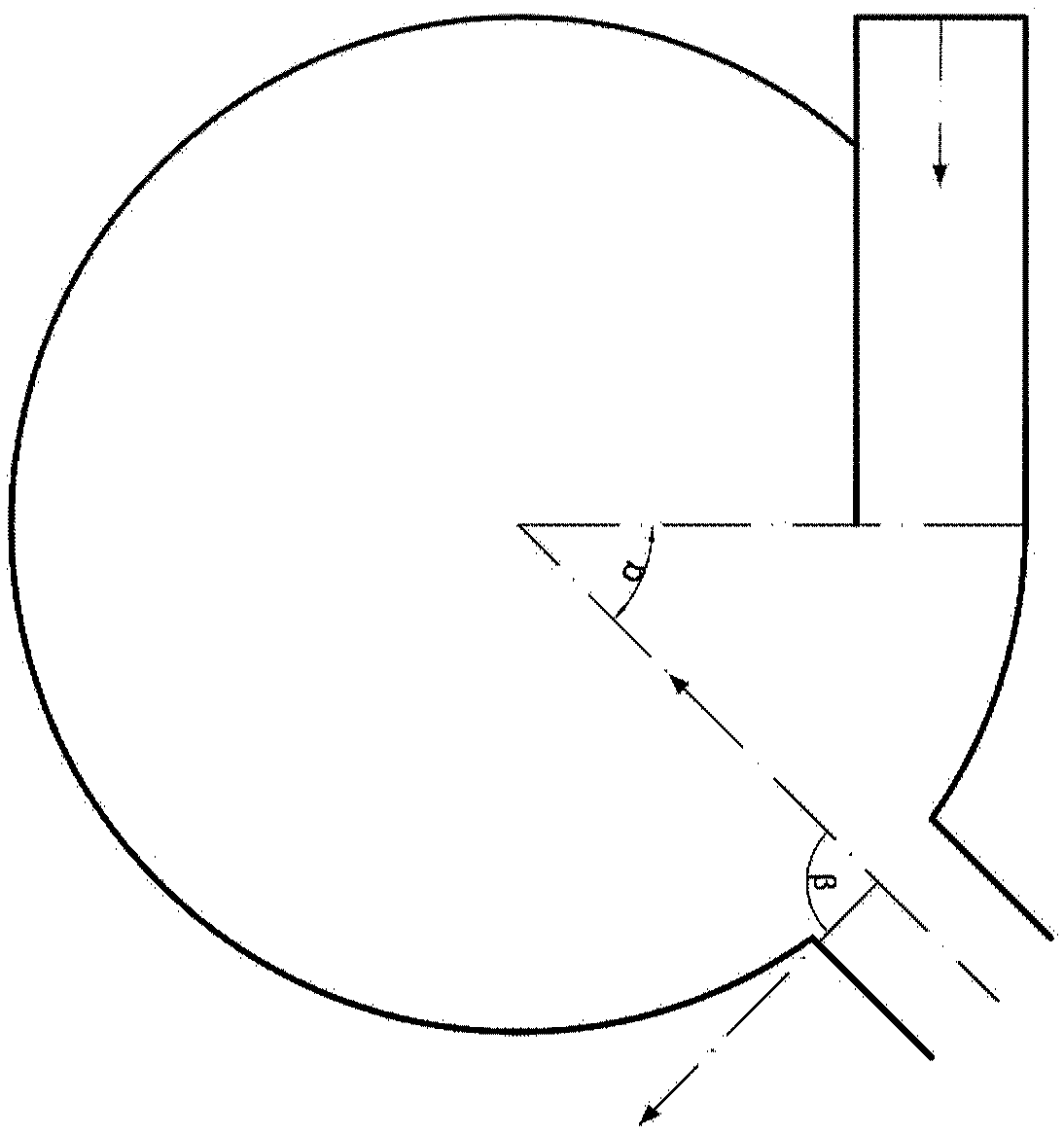
Figure 1 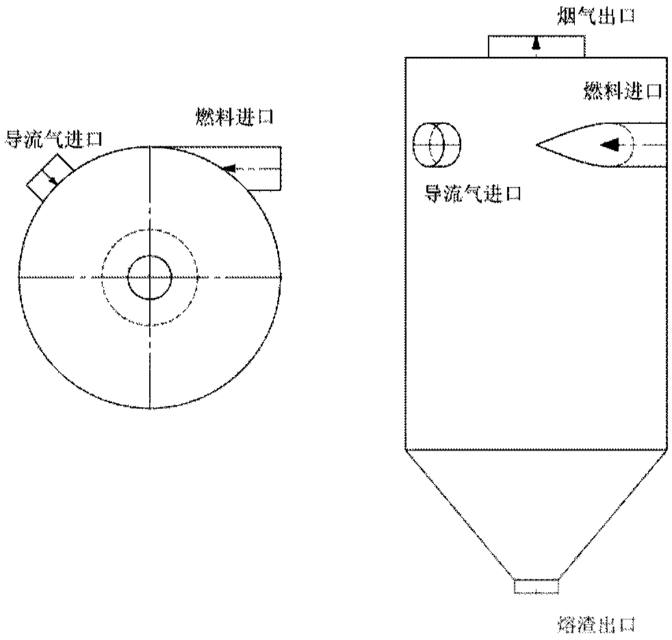
Figure 2 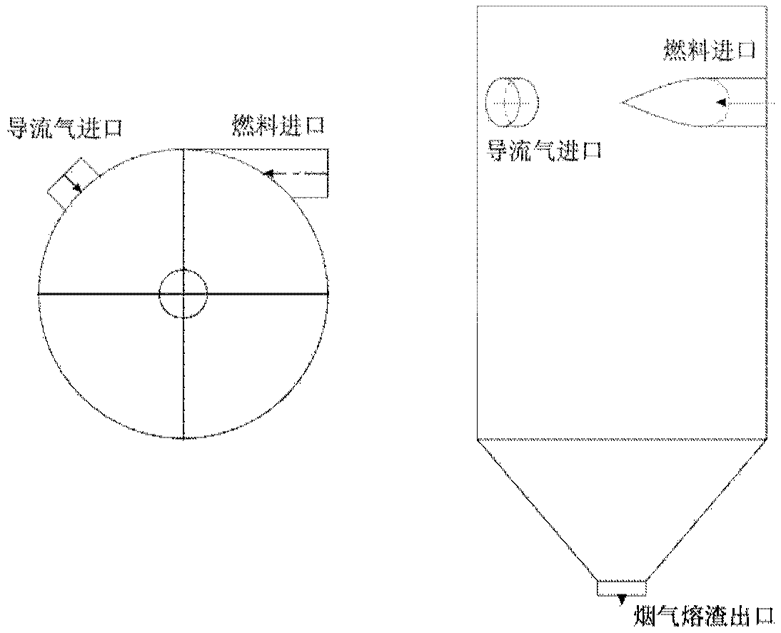
Figure 3
Abstract
Description
technical field
[0001] The invention belongs to the application field of cyclone melting furnaces, and in particular relates to a method for reducing wear of refractory materials of ultra-low volatile carbon-based fuels and waste cyclone liquid slagging furnaces by using the cyclone melting furnace. Background technique
[0002] High-temperature melting furnaces are widely used in many fields. In the high-temperature melting reaction of combustible gasification fine powder ash and ash, it can make the carbon with poor reactivity contained in combustible gasification fine powder ash and ash and oxidant in the Fully react under high temperature conditions, increase the carbon conversion rate, and obtain slag water-cooled crystallization to form a harmless glass body.
[0003] In the prior art, the burners are arranged tangentially on the side of the furnace. The cyclone melting furnace uses the high-speed rotating air flow to rotate the coal particles at a high speed and burn ...
Examples
Embodiment Construction
[0031] In order to make the object, technical solution and advantages of the present invention clearer, the present invention will be further described in detail below in conjunction with specific embodiments and with reference to the accompanying drawings. Hereinafter, some examples will be provided to illustrate the embodiments of the present invention in detail. The advantages and effects of the present invention will be more obvious through the following content of the present invention. The drawings accompanying this description are simplified and used for illustration purposes. The number, shape and size of the components shown in the drawings can be modified according to the actual situation, and the configuration of the components may be more complicated. Other aspects of practice or application can also be carried out in the present invention, and various changes and adjustments can be made without departing from the defined spirit and scope of the present invention....