

Stair deflection testing tool
A technology for testing tooling and steps, which is applied in the direction of measuring devices, testing of machines/structural components, instruments, etc., can solve problems such as complex structure, inconvenient installation, and inability to meet step tests, and achieve high versatility, easy movement, and increased versatility The effect of sex and convenience
Patent Information
- Authority / Receiving Office
- CN · China
- Patent Type
- Applications(China)
- Current Assignee / Owner
- Publication Date
- 2019-11-08
Smart Images
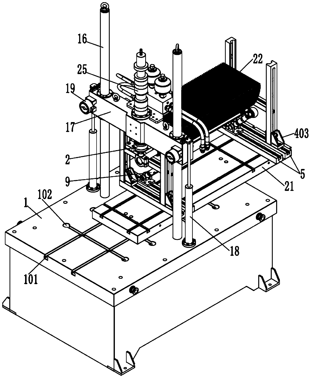
Figure 1 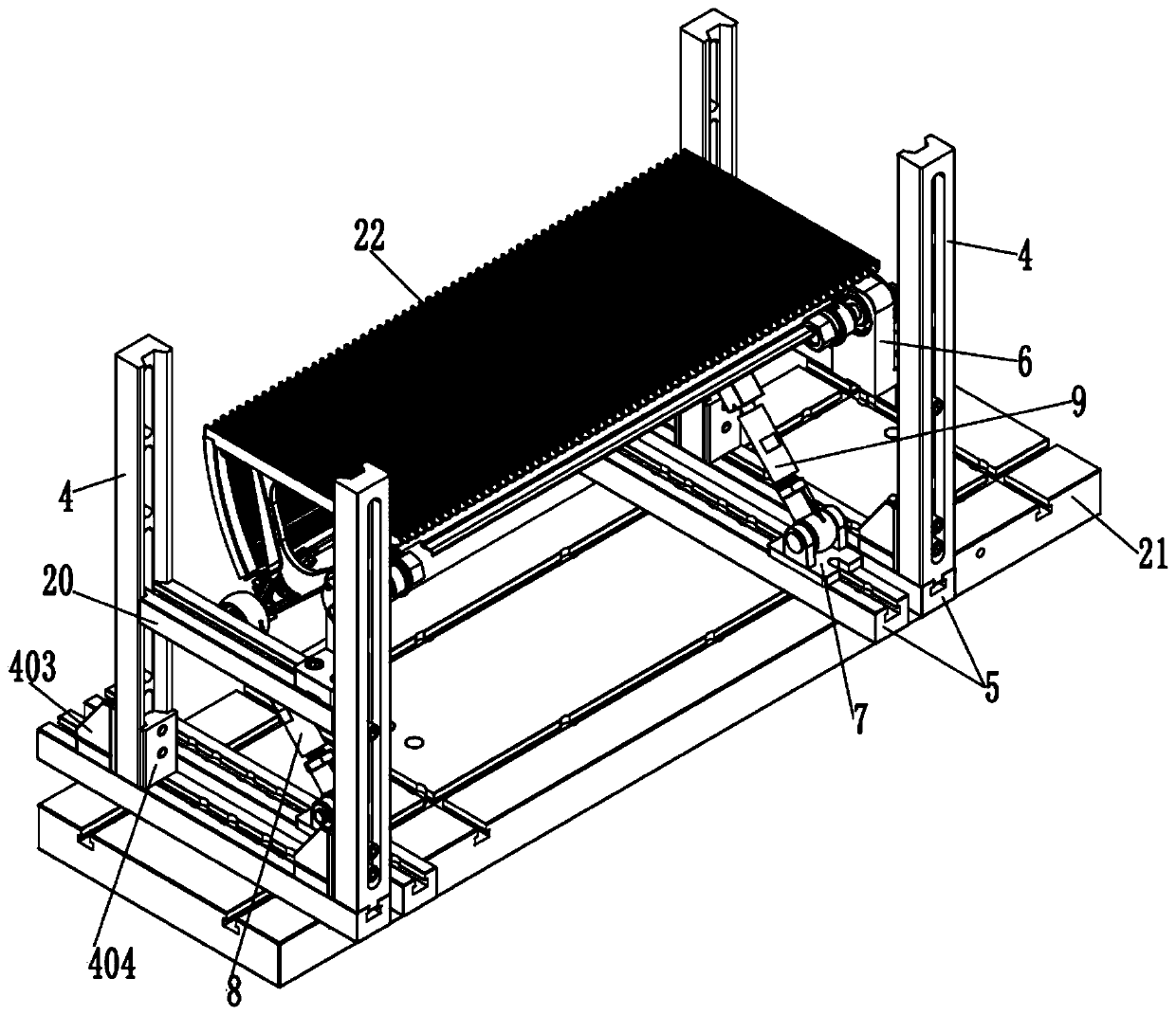
Figure 2 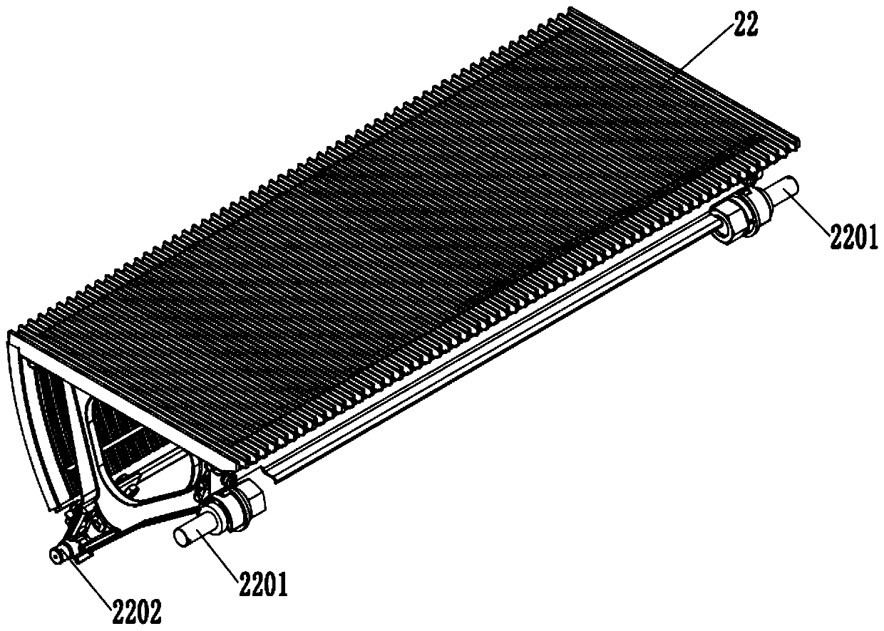
Figure 3
Abstract
Description
technical field
[0001] The invention relates to the technical field of step testing, in particular to a step deflection testing tool. Background technique
[0002] The steps are the components that circulate on the escalator truss for passengers to stand on. These steps are generally assembled and combined by pedals, kick plates, brackets, sprocket shafts, step tugs, and step sprockets. Existing step test equipment conducts deflection tests on the steps, and by simulating people stepping on the steps, it is tested how much deformation or failure the steps will produce under the action of force in the worst environment. According to the requirements of relevant standards, the steps need to be tested in various ways, and the installation methods of the steps may be different for different test methods. However, the existing step test equipment has a complex structure and is inconvenient to install, which is far from meeting the relevant requirements of the step test. Conten...
Examples
Embodiment 1
[0046] Such as Figure 1-Figure 14 A step deflection test tooling shown includes a workbench 1, a clamping mechanism, a support mechanism, a test drive mechanism, a sensor 2 and a step indenter head 3; the support mechanism is installed on the upper surface of the workbench 1, and the The test driving mechanism is installed on the support mechanism, the sensor 2 is installed on the output end of the test driving mechanism, and the clamping mechanism is installed on the upper surface of the workbench 1. The clamping mechanism is used to limit the step parts, and the step pressure head Part 3 includes a joint bearing sleeve 301 and a final shaft 302, the joint bearing sleeve 301 is connected to the output end of the test drive mechanism, one end of the final shaft 302 is connected to the joint bearing sleeve 301, and the other end of the final shaft 302 is connected to the clamping mechanism connected, the sensor 2 is connected to the final shaft 302.
[0047] Such as Figure ...
Embodiment 2
[0066] This embodiment is the same as embodiment 1 except the following technical features:
[0067] Such as Figure 15-23 As shown, the clamping frame includes a bottom support layer, a column 4 and a first beam 20; the bottom support layer is slidably arranged on the workbench 1, and two columns 4 are relatively installed on the bottom support layer. The two ends of the first beam 20 are respectively connected with the two uprights 4; the clamping assembly includes the second beam 10, the rocker arm 11, the second chain shaft positioning seat 12, the wedge-shaped locking member 13, and the first roller seat 14, the second supporting roller seat frame 24 and the sliding iron 15; the bottom support layers of the two clamping frames are equipped with the first supporting roller seat frame 14, and the two ends of the second beam 10 are clamped with one of them The two columns 4 of the frame are connected, the second beam 10 is located above the first beam 20 of the clamping fra...