
Rotary table bearing with high limit speed
A technology for limiting rotational speed and turntable bearings, applied in the field of bearings, it can solve the problems of temperature rise in the bearing raceway, burns of parts such as raceways and rollers, spin motion of cylindrical rollers, etc., and achieve edge contact stress reduction and service life. The effect of prolongation and speed increase
Patent Information
- Authority / Receiving Office
- CN · China
- Patent Type
- Applications(China)
- Current Assignee / Owner
- Publication Date
- 2019-12-06
Smart Images
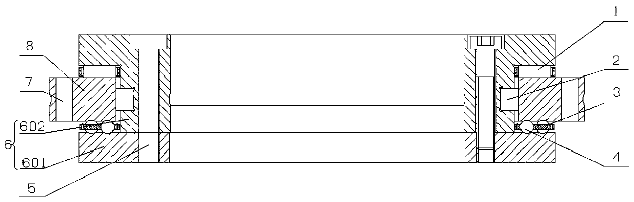
Figure 1 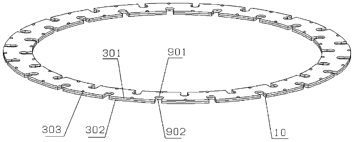
Figure 2 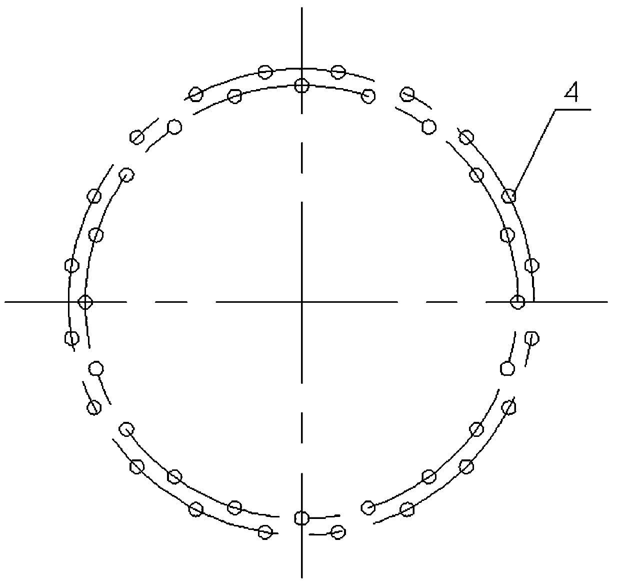
Figure 3
Abstract
Description
technical field
[0001] The invention relates to the field of bearings, in particular to a turntable bearing with a high limit speed. Background technique
[0002] The traditional turntable bearing is a three-row combined roller bearing, which is composed of two thrust cylindrical roller bearings and a full complement radial cylindrical roller bearing. The upper and lower rows of axial rollers of this kind of bearing will have a speed difference between the two ends during the rotation process, which will lead to the occurrence of cylindrical roller spin motion, and then form sliding friction, which makes the friction torque of the bearing larger and the limit operating speed lower. Once the bearing speed is too high, the temperature of the raceway of the bearing will rise sharply, causing burns to parts such as raceways and rollers. However, with the increasing speed of CNC machine tools, the speed requirements of CNC turntables are also increasing, and the traditional tur...
Examples
Embodiment Construction
[0026] Such as figure 1 As shown, a turntable bearing with a high limit speed of the present invention is similar in main structure to a conventional turntable bearing, both including an inner ring 6 and an outer ring 8 rotatably arranged on the outer periphery of the inner ring 6 . The outer ring 8 is ring-shaped, and the inner ring 6 is I-shaped. The upper edge of the outer ring 8 and the lower edge of the upper end of the inner ring 6 are matched by a plurality of first rolling elements 1. The inner edge of the outer ring 8 and the middle part of the inner ring 6 The outer edge of the outer ring is matched by a plurality of second rolling elements 2, and the lower edge of the outer ring 8 is matched with the upper edge of the lower end of the inner ring 6 by a plurality of third rolling elements 4. For ease of assembly, the inner ring 6 is split and includes an upper ring 602 and a lower ring 601 . The outer ring 8 is provided with a first installation hole 7 for fixing th...