

Preparation process of an explosion-proof magnetostrictive liquid level gauge
A magnetostrictive liquid level and preparation technology, which is applied in the direction of buoy liquid level indicators, etc., can solve the problems of the sharp increase in the cost of magnetostrictive liquid level gauges, the very high straightness requirements of waveguide wires, and the high cost of imported waveguide wires. , to achieve good insulation, high hardness, and reduce storage space and length requirements
Patent Information
- Authority / Receiving Office
- CN · China
- Patent Type
- Patents(China)
- Current Assignee / Owner
- Publication Date
- 2021-09-03
Smart Images
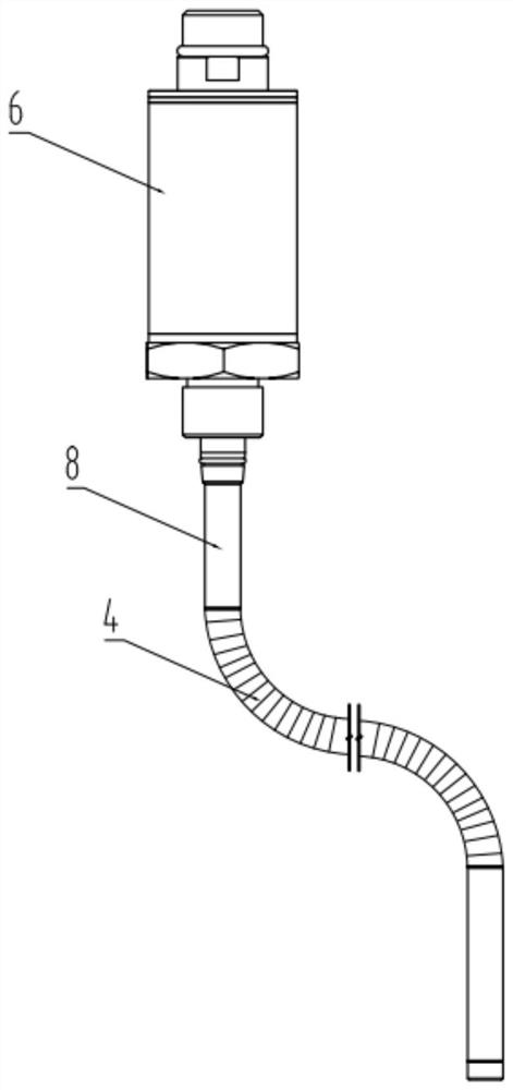
Figure 1 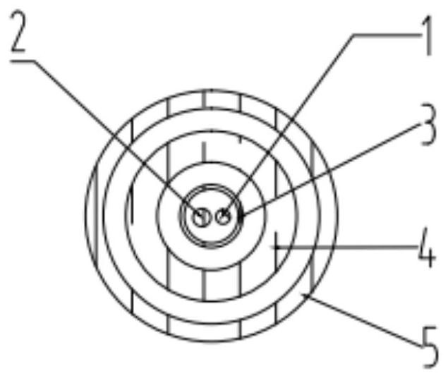
Figure 2 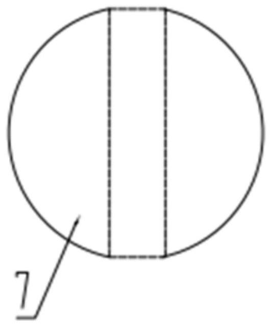
Figure 3
Abstract
Description
technical field
[0001] The invention belongs to the technical field of liquid level measurement, and relates to a preparation process of a liquid level gauge, in particular to a preparation process of an explosion-proof magnetostrictive liquid level gauge. Background technique
[0002] In flammable and explosive environments such as oil and gas exploration and petrochemical industries, the measurement of the oil volume of oil tanks is mostly performed by manually climbing the tank and measuring with a ruler. Use a metric steel tape tape with a heavy hammer or a scale with a scale to measure, manually record the readings, manually look up the table for conversion, and finally get the oil quantity data. This measurement method is not only labor-intensive, but also has unsafe factors and cannot guarantee accuracy.
[0003] There are several existing liquid level gauges, mainly including: ① capacitive type, diffused silicon pressure type liquid level gauge, this kind of sensor ...
Examples
Embodiment Construction
[0028] Below in conjunction with accompanying drawing and embodiment the present invention is described in further detail:
[0029] The invention provides a preparation process of an explosion-proof magnetostrictive liquid level gauge, comprising the following steps,
[0030] Step 1): Weld waveguide wire 1 and feeder 2, weld one end of waveguide wire 1 and feeder 2, and penetrate into inner protection tube 3 in parallel, and protect the welding spot of waveguide wire 1 and feeder 2 with a heat shrinkable tube;
[0031] Step 2): Insert the inner protective tube 3 into the bellows 4, and then insert the bellows 4 into the outer protective tube 5;
[0032] Step 3): The bellows 4 is welded to the steel pipe 8, and the inner protection tube 3 and the electronic compartment 6 are fixedly connected;
[0033] Step 4): the steel pipe 8 is welded to the electronic warehouse 6;
[0034] Step 5) The magnetic floating ball 7 is installed on the outside of the outer protection tube 5. The...