
Friction plate assembly, braking device and motor
A friction plate and brake technology, applied in the direction of brake types, brake actuators, brake components, etc., can solve the problems of brake braking performance failure, long brake response time, abnormal wear, etc., to reduce the actual braking time, The effect of improving work efficiency and reducing overall power
Patent Information
- Authority / Receiving Office
- CN · China
- Patent Type
- Applications(China)
- Current Assignee / Owner
- Publication Date
- 2020-01-03
Smart Images
Figure 1 
Figure 2 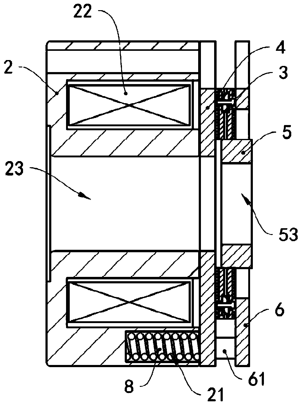
Figure 3
Abstract
Description
technical field
[0001] The invention relates to the technical field of brakes, in particular to a friction plate assembly, a brake and a motor. Background technique
[0002] The brake is an important basic component, which integrates mechanical, electrical and electronic technologies, and is mainly used for precise control and braking of rotating mechanisms such as motors. The brake is installed in the servo motor. When the servo motor is working, if the response time of the brake is long, and the response time of the brake is longer than the response time of the motor, then the motor starts and the brake does not start, which will cause abnormal wear of the brake, brake failure, and potential safety hazards. . At the same time, since the friction plate is a non-rigid material, during the braking process, the friction plate will rotate several times, and the friction will work until the braking is completed. During this process, the friction plate will deflect the angle, ca...
Examples
Embodiment Construction
[0039] The motor in this embodiment includes a brake and a motor shaft.
[0040] see image 3 , the brake includes a stator 2, a friction plate assembly 3, an armature 4, a square wheel 5, a baffle plate 6, and a second elastic member 7 ( Image 6 shown) and spring 8. One side of the baffle plate 6 is provided with a connecting column 61, one end of the connecting column 61 is fixedly connected to the baffle plate 6, the other end of the connecting column 61 is fixedly connected to the stator 2, the armature 4 is sleeved on the connecting column 61, and the armature 4 can be Sliding along the extension direction of the connecting column 61 , the friction plate assembly 3 is installed between the armature 4 and the baffle plate 6 . Stator 2 is provided with axle hole 23, and square wheel 5 is provided with fixing hole 53, and fixing hole 53 and axle hole 23 are coaxially arranged, and motor rotating shaft passes through axle hole 23 and fixing hole 53 successively, and motor ...