
Method for adjusting an operating point of a hydraulic actuator arrangement
A technology of operating points and facilities, applied in the direction of mechanical equipment, components with teeth, transmission device control, etc., can solve the problem that the operating points cannot be adjusted correctly, and achieve the effect of direct connection
Patent Information
- Authority / Receiving Office
- CN · China
- Patent Type
- Applications(China)
- Current Assignee / Owner
- Publication Date
- 2020-01-14
Smart Images
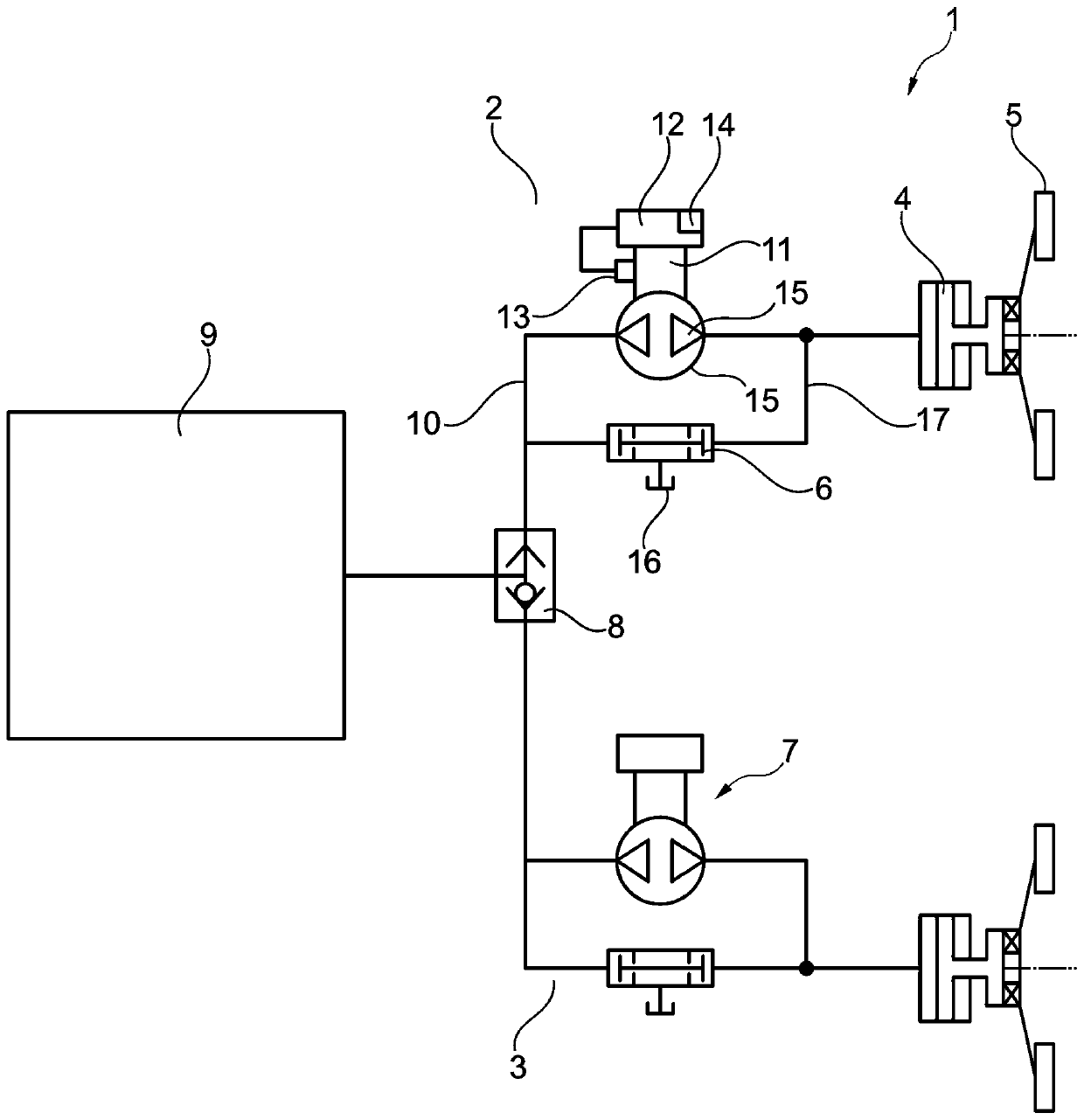
Figure 1 
Figure 2 
Figure 3
Abstract
Description
technical field
[0001] The invention relates to a method for setting the operating point of a hydraulic actuator, wherein a volume flow source is connected to a hydraulic cylinder via a pressure line filled with hydraulic fluid, wherein the volume of the hydraulic fluid is regulated by the volume flow source and operated The point corresponds to the positioning of the execution facility under predetermined parameters of the device to be operated by the execution facility, wherein from the rotational position of the volume flow source motor and / or the volume flow source the required hydraulic fluid for setting the operating point is derived. volume. Background technique
[0002] From WO 2016 / 141935 A1 a method for setting and adjusting the operating point of a hydraulic actuating device is known. Here, hydraulic actuation devices are used to actuate the clutch. The volume flow source, which is configured as a pump, is connected via a hydraulic line to a hydraulic cylinder, ...
Examples
Embodiment Construction
[0020] specific implementation
[0021] figure 1 , the pump actuator 1 is constructed as a dual-motor dual-clutch transmission. In the dual clutch transmission there are two sub-branches 2 , 3 , both of which comprise hydraulic cylinders 4 which actuate the clutch 5 . The respective hydraulic cylinder 4 of the clutch 5 is actuated via a dual-pressure valve 6 which is coupled to a pump actuator 7 . The two sub-branches 2 , 3 are connected to a transmission actuator 9 via a valve 8 .
[0022] Since the two sub-branches 2, 3 are constructed identically, only one sub-branch needs to be described. In each sub-branch 2 , 3 the line 10 is connected to a pump actuator 7 , which is driven by an electric motor 11 . The electric motor 11 is in turn driven by the control device 12 . Used to know the angular increment passed by the electric motor 11 The sensor 13 is arranged on the electric motor 11 . The switching signals of the sensor 13 are counted by a counter 14 arranged in th...