

A pre-charge control device and method
A control device and pre-charging technology, applied in the direction of circuit devices, battery circuit devices, collectors, etc., can solve the problems of slow pre-charging speed, slow rising speed, low pre-charging efficiency, etc., and achieve the effect of increasing speed and improving efficiency
Patent Information
- Authority / Receiving Office
- CN · China
- Patent Type
- Patents(China)
- Current Assignee / Owner
- Publication Date
- 2022-03-29
Smart Images
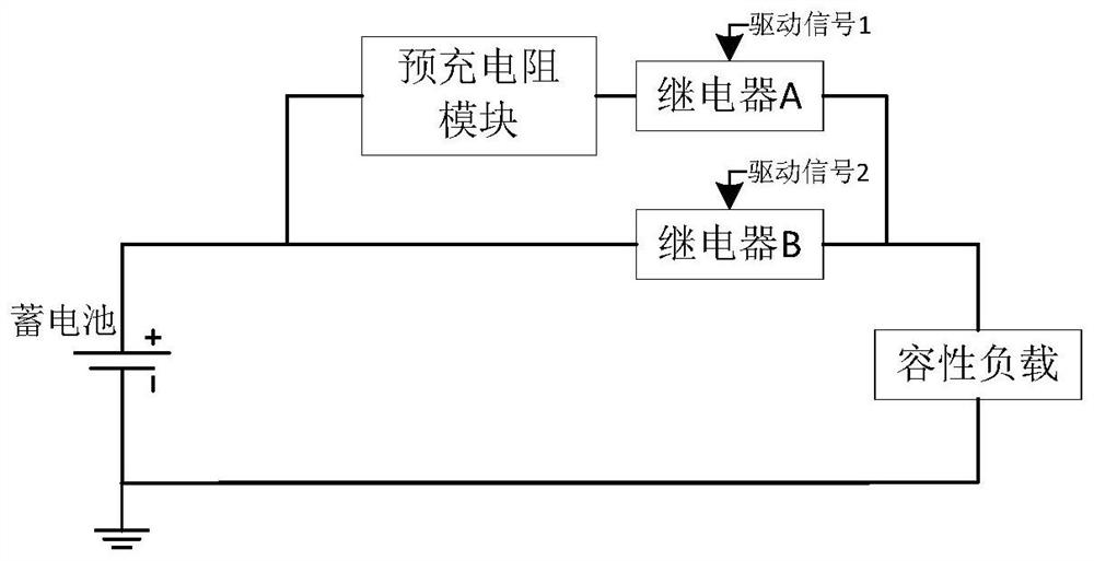
Figure 1 
Figure 2 
Figure 3
Abstract
Description
technical field
[0001] The invention relates to the technical field of power supply control, in particular to a pre-charging control device and method. Background technique
[0002] Currently, battery-powered mobile devices such as intelligent mobile robots and electric vehicles have been widely used. These devices mostly use higher-voltage batteries to supply power to the load, and when the battery supplies power, an instantaneous large charging current will be generated for the load of the device. For example, for an intelligent mobile robot, it uses a 48V battery to power the entire circuit, and there is a capacitive load with a large capacity. When the battery is powered, a large charging current is generated, which is likely to cause damage to system-related components. In order to solve this problem, a pre-charging control technical solution is proposed in the related art.
[0003] Such as figure 1 As shown, the dual-relay resistance scheme can be adopted, in which ...
Examples
Embodiment Construction
[0053] In order to make the purpose, technical solution and advantages of the present invention more clear, the present invention will be further described in detail below with reference to the accompanying drawings and examples.
[0054] Such as image 3As shown, the precharge control device 1 of the present invention is arranged between the storage battery 2 and the capacitive load 3 . Wherein, the precharge control device 1 includes a resistance precharge branch 11, a linear precharge branch 12, a power supply branch 13 and a voltage sampling control module (not shown in the figure), the resistance precharge branch 11, the linear precharge branch The circuit 12 and the power supply branch circuit 13 are connected in parallel between the storage battery 2 and the capacitive load 3 . Among them, the resistance pre-charging branch 11 is turned on or off under the driving of the first driving signal, the linear pre-charging branch 12 is turned on or off under the driving of th...