
Anti-shake system for miniature camera shooting
A micro-camera and anti-shake technology, which is applied to the focusing device of the projector, the focusing device of the camera, and optics, etc., can solve the problems of blurred images, complicated procedures, and high costs, and achieve rapid increase in production capacity and rapid and accurate production , cost reduction effect
Patent Information
- Authority / Receiving Office
- CN · China
- Patent Type
- Applications(China)
- Current Assignee / Owner
- Publication Date
- 2020-07-21
Smart Images
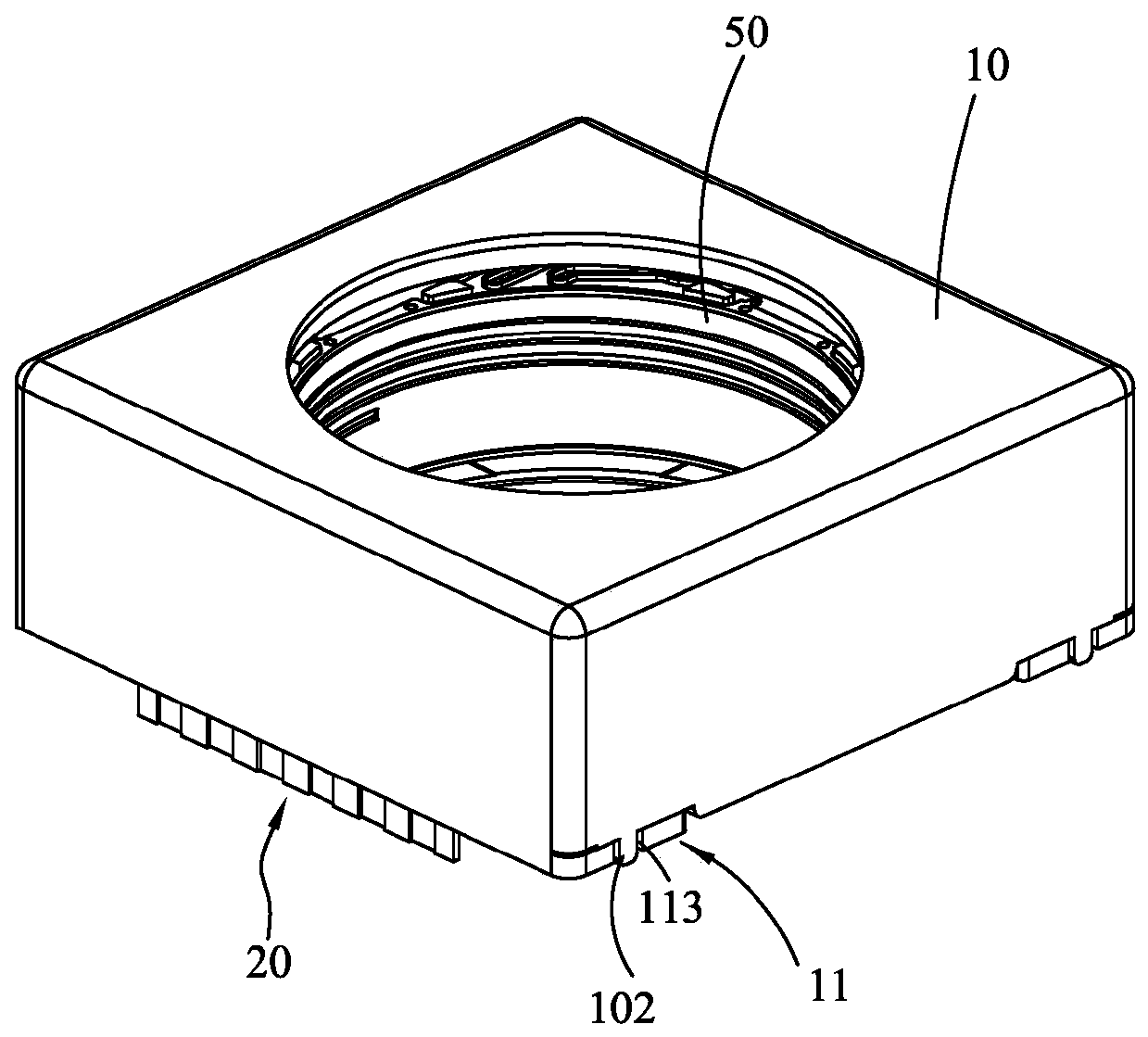
Figure 1 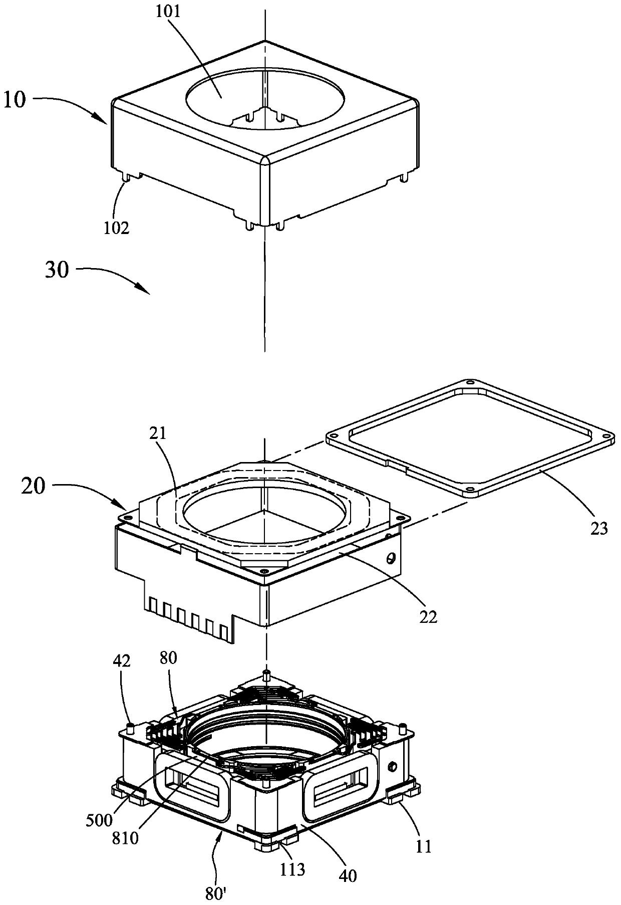
Figure 2 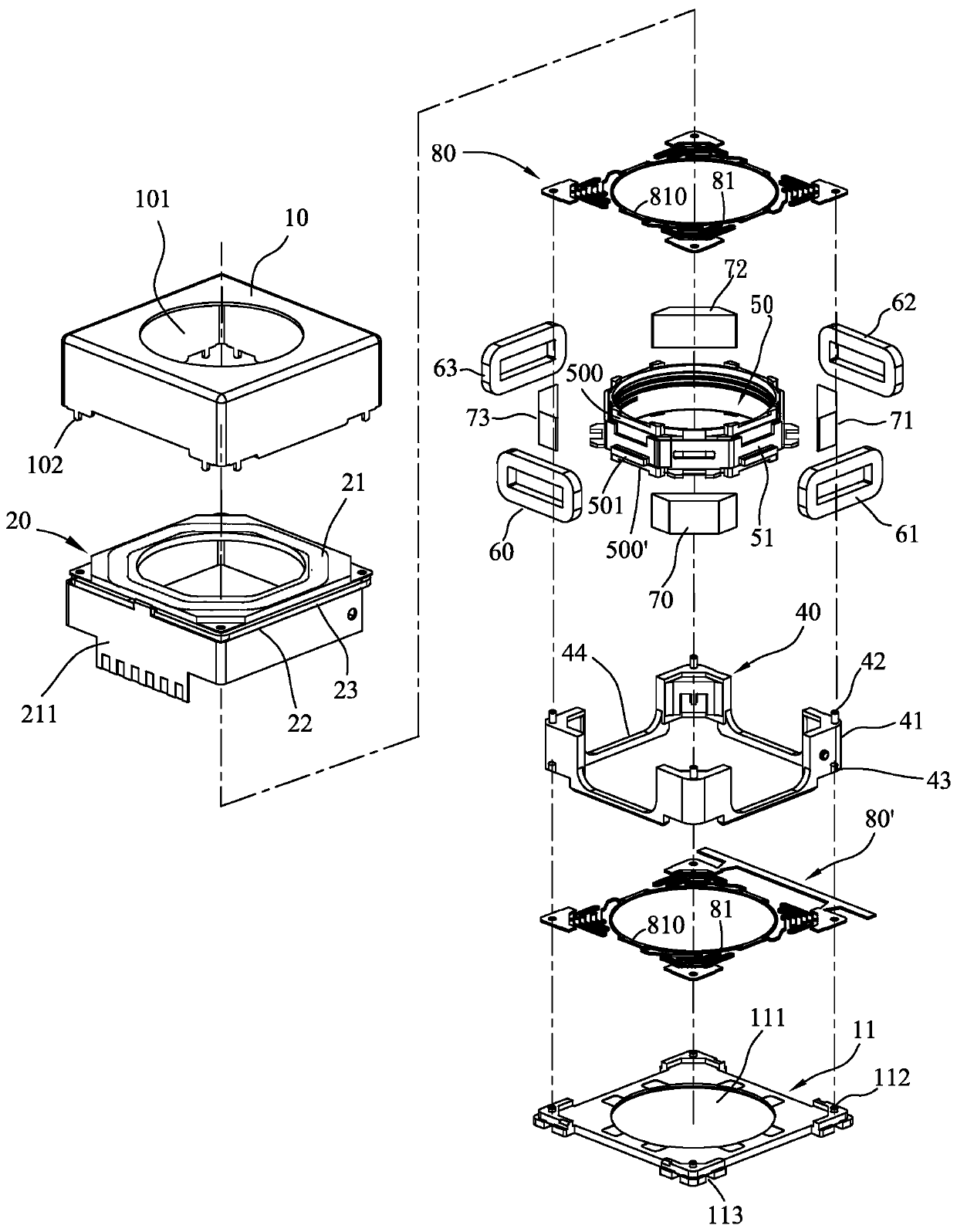
Figure 3
Abstract
Description
technical field
[0001] The invention relates to an anti-shake system for miniature cameras, in particular to an anti-shake focusing motor device that can be used as a three-dimensional three-axis magnetic circuit system, which can be widely used in miniature photographic equipment or matched with mobile phone camera systems Equipped, it has the advantages of saving parts and assembly costs, and not occupying a volume. Background technique
[0002] While photographic devices are becoming thinner and smaller, the technology of motors for micro-camera modules is becoming more and more important. Especially when mobile phones become an indispensable item in life, the need for micro-motors on mobile phones is even greater. Therefore, the requirements for the anti-shake technology of micro motors are constantly increasing.
[0003] The Optical Image Stabilization (OIS) in the camera mainly uses the internal lens or photosensitive element to correct the movement of the camera such...
Examples
Embodiment Construction
[0056] Please see figure 1 , figure 2 , image 3 As shown, the present invention at least includes:
[0057] A non-magnetic permeable upper cover 10 and a base 11 all have a middle hole 101, 111, which can be fitted with nail claws 102 and buckle grooves 113 to form the outer shell of the anti-shock system; wherein the base 11 and There are stud posts 112 combined with internal components at four corners.
[0058] A flexible circuit board 20, located in the inside of the outer shell, has a flexible board coil 21 in a horizontal direction, and a vertical circuit substrate 211 connected by the side of the flexible board coil 21, and the flexible board coil 21 and the circuit A gap 22 is formed between the substrates 211; a spacer 23 is accommodated in the gap 22 to provide a movable stroke of the mover part in the Z-axis movement direction; image 3 The shown flexible circuit board 20 is connected with a vertical circuit substrate 211 surrounded by four sides by one side o...