
Flexible grounding mode power distribution network grounding fault direction algorithm
A grounding fault and grounding method technology, applied in the fault location, detecting faults according to the conductor type, measuring electricity and other directions, can solve the problems such as the protection method is not suitable for flexible grounding methods, insufficient utilization of fault characteristics, and difference in fault characteristics, etc. Line efficiency, high resistance to transition resistance, and low communication stress
Patent Information
- Authority / Receiving Office
- CN · China
- Patent Type
- Applications(China)
- Current Assignee / Owner
- Publication Date
- 2020-08-14
Smart Images
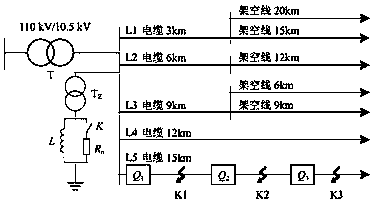
Figure 1 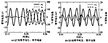
Figure 2 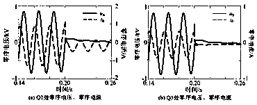
Figure 3
Abstract
Description
technical field
[0001] The invention belongs to the field of distribution network fault detection and protection, in particular to a flexible grounding mode distribution network grounding fault direction algorithm. Background technique
[0002] In order to automatically extinguish the arc of most ground faults and reliably remove permanent faults, and reduce the impact of ground faults on the distribution network, China Southern Power Grid Corporation proposed a flexible grounding method in which the arc-suppression coil is connected in parallel with a small resistance, referred to as the flexible grounding method. Relevant regulations have promulgated the "Technical Specifications for Arc Suppression Coil Parallel Small Resistance Grounding Device (Draft for Comment)", and the State Grid Corporation of China is also conducting relevant demonstrations. The basic idea of the flexible grounding method is to rely on the arc suppressing coil to compensate the fault current at ...
Examples
Embodiment Construction
[0020] The present invention will be described in further detail below in conjunction with the accompanying drawings and embodiments.
[0021] A flexible grounding method distribution network grounding direction algorithm, its fault direction identification process is as follows figure 1 As shown, the details are as follows:
[0022] Step 1: Start the device, measure the effective value of zero-sequence voltage and zero-sequence current in the current period, and calculate the admittance modulus value of zero-sequence measurement, and store it in Y 1 ;
[0023] Step 2: Measure the effective value of the zero-sequence voltage and the effective value of the zero-sequence current in the next cycle, if the effective value of the zero-sequence voltage is not less than U set (this embodiment takes 120V), further calculate the zero-sequence measurement admittance, and store it in Y 2 , go to step 4; otherwise, go to step 3;
[0024] Step 3: If the effective value of the zero-seq...