
Self-checking device and method for water flow control device
A technology of self-checking device and water flow control, applied in the direction of valve device, valve operation/release device, valve details, etc., can solve the problem of loss of closing function, etc., achieve the effect of saving labor, saving water resources, and avoiding damage
Patent Information
- Authority / Receiving Office
- CN · China
- Patent Type
- Applications(China)
- Current Assignee / Owner
- Publication Date
- 2021-02-23
Smart Images
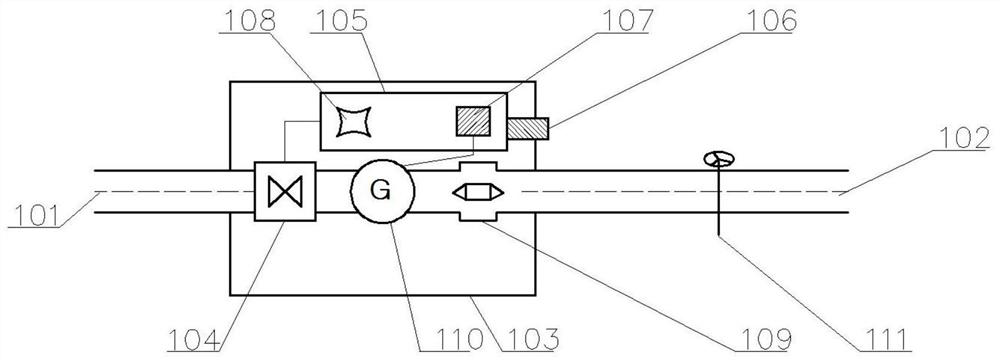
Figure 1 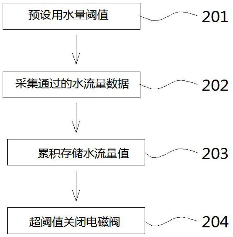
Figure 2 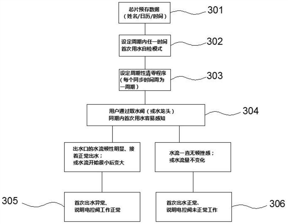
Figure 3
Abstract
Description
technical field
[0001] The invention relates to the field of switch control, in particular to a self-checking device of a water flow control device and a method for using the same. Background technique
[0002] Water, without a doubt, is very important to most living individuals! Water is an important resource on the earth where we live, and it is of great significance to human beings. In general, the water consumption of water installations is predictable. Generally, household water is about 1000-6000 liters a day. If the water device fails to close the valve or faucet, the water will continue to flow out, which will not only cause waste of water resources, but what is even worse is that the indoor water will damage the home floor and damage the furniture. Appliances, causing more serious property damage. Some floor dwellings even leak water for a long time due to broken water pipes and other reasons, and it has not been discovered that it has caused disasters to other p...
Examples
Embodiment 1
[0048] like figure 1 As shown, the self-inspection device of a water flow control device provided in this embodiment is a self-inspection device of a water flow control device, which includes water pipes 101 and 102 through which the water flows. A fluid electric control valve 104, an intelligent control module 105, a water flow sensor 109, and a water intake valve 111 are provided. The water intake valve 111 is a terminal for users to obtain water, and the intelligent control module 105 is provided with a power supply 107 for providing energy;
[0049] The intelligent control module 105 is used to power off the fluid electric control valve 104 and close the water flow when it is judged that the accumulated water flow value of the water flow sensor 109 exceeds a preset threshold;
[0050] The power supply 107 is connected to the fluid electric control valve 104, the intelligent control module 105, and the water flow sensor 109 respectively, and is used to provide power for the...
Embodiment 2
[0053] like figure 1 and figure 2 As shown, similar to Embodiment 1, in this embodiment, the chip 108 pre-stores data, is located on the intelligent control module 105, and controls the fluid electronic control valve 104 through the intelligent control module 105;
[0054] The water intake valve 111 is a quick-open valve, including a faucet that can reach the maximum flow of water when the angle is not more than 90°;
[0055] The water pipe passes through the box body 103 through the through holes on both sides of the box body 103, and the water flow in the water pipe flows from the water pipe inlet 101 on the outer side of the box body 103 to the water pipe outlet 102 on the other side of the box body 103;
[0056] The right side of the intelligent control module 105 is provided with a manual reset key 106, which is used to manually restore the normal reset of the entire water control device including the fluid electric control valve 104; The through hole is installed on t...
Embodiment 3
[0058] like figure 1 and figure 2 As shown, similar to Embodiment 1, in this embodiment, the power source 107 provided in the intelligent control module 105 is an energy storage power source, including a battery pack. The present embodiment is also provided with a generator 110 installed in the casing 103, and the generator 110 is connected to the power supply 107;
[0059] The generator 110 relies on the kinetic energy of flowing water flowing from the water pipe inlet 101 to the water pipe outlet 102 to generate electricity by itself, and the generated electric energy is stored in the power source 107 .