
An outdoor power distribution cabinet
A power distribution cabinet and outdoor technology, applied in substation/power distribution device casing, electrical components, door/window accessories, etc., can solve problems such as inconvenient operation, inability to effectively block rain, troubles, etc., and achieve the effect of improving convenience
Patent Information
- Authority / Receiving Office
- CN · China
- Patent Type
- Patents(China)
- Current Assignee / Owner
- Publication Date
- 2022-07-22
Smart Images
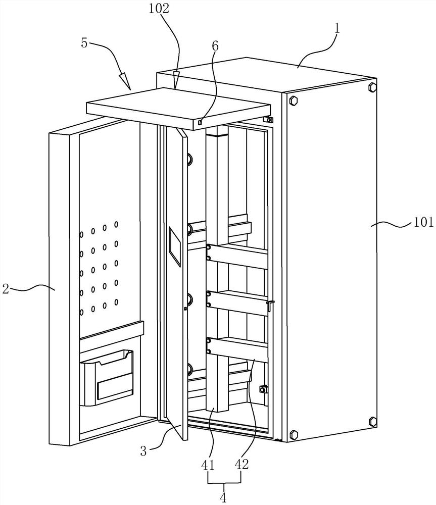
Figure 1 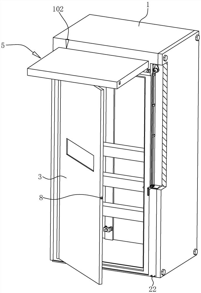
Figure 2 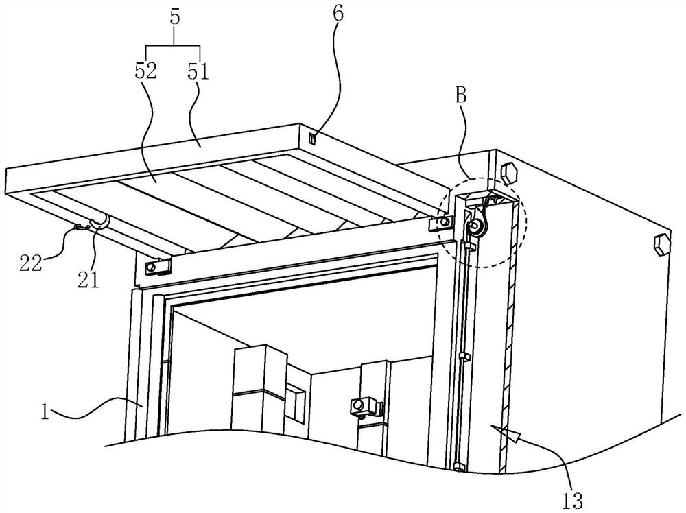
Figure 3
Abstract
Description
technical field
[0001] The present application relates to the technical field of power distribution equipment, in particular to an outdoor power distribution cabinet. Background technique
[0002] The power distribution cabinet is a common power control equipment. The low-voltage power distribution cabinet is used for power conversion and control of lighting and power distribution, and has a wide range of applications. The shell structure of the low-voltage cabinet directly affects the on-site installation of power to a large extent. With the current various forms of power construction, whether the on-site construction and installation of the low-voltage power distribution cabinet is convenient greatly affects the investment of resources in power construction.
[0003] For example, the Chinese patent with the publication number CN203800414U in the related art discloses an electric shock-proof double-door power distribution cabinet, which includes a cabinet body and a double-...
Examples
Embodiment Construction
[0040] Attached to the following Figure 1-8 This application will be described in further detail.
[0041] The embodiments of the present application disclose an outdoor power distribution cabinet. refer to figure 1 and figure 2 , which includes a cuboid-shaped cabinet 1 and an outer door 2 and an inner door 3 pivotally connected to the open side of the cabinet 1 from outside to inside, and an outer door 2 lock is installed between the outer door 2 and the cabinet 1 . At the same time, a mounting frame 4 is fixedly installed inside the cabinet body 1 . Specifically, the mounting frame 4 includes a pair of vertical columns 41 parallel to each other and a plurality of cross bars fixedly connected between the two columns 41 by screws. 42 , the plurality of horizontal bars 42 are arranged horizontally, and the plurality of horizontal bars 42 are distributed at equal intervals along the length direction of the upright column 41 . In addition, a plurality of screw holes (not s...