
Pressure regulating chamber device for hydropower station
A technology for surge chambers and hydropower stations, which is applied in hydropower stations, hydropower, water conservancy projects, etc. It can solve problems affecting structural safety, water hammer pressure loss, and general energy dissipation effects, so as to improve the mechanical performance of structures and reduce Water hammer pressure, avoiding the effect of excessive local pressure
Patent Information
- Authority / Receiving Office
- CN · China
- Patent Type
- Applications(China)
- Current Assignee / Owner
- Publication Date
- 2021-04-09
Smart Images
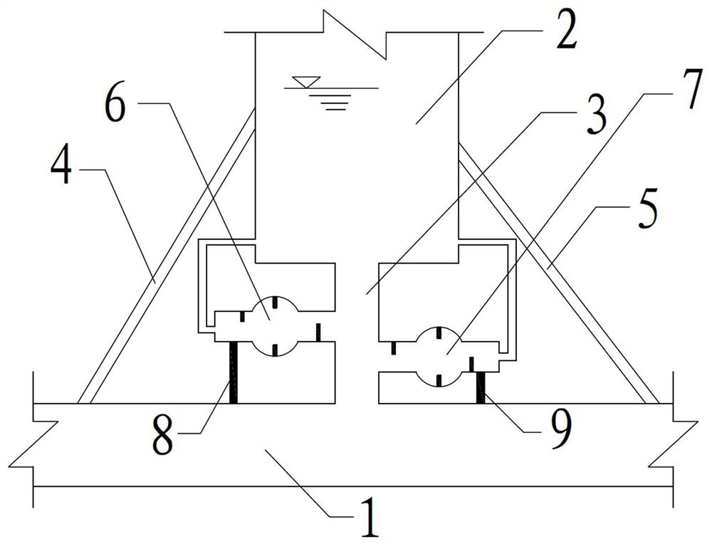
Figure 1 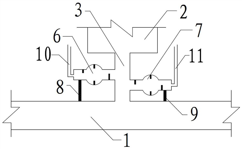
Figure 2 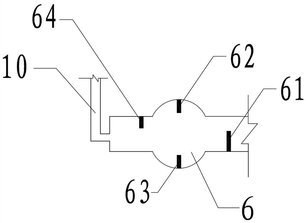
Figure 3
Abstract
Description
Technical field
[0001] The present invention relates to the field of water conservancy engineering, and more particularly to a pressure regulating chamber device for hydropower stations.Background technique
[0002] The pressure regulating chamber structure is a pressure regulating regulator, which is commonly used in hydropower stations. Since the hydropower station is long, once the unit emergency stop or suddenly reduces the opening degree, it is easy to generate a certain water shock pressure in the pressure pipe, and the hydrotential pressure exceeds the hydropower station pressure. When the pipe is allowed to stress, it will cause damage to the pressure pipeline, causing safety hazards.
[0003] When the pressure of the hydropower pipe pressure pipeline is controlled, there is a multi-use extension unit to turn off the start and stop, and increase the strength of pressure pipeline, the pressure regulating room structure is an important engineering measures that effectively reduce the pr...
Examples
specific Embodiment approach
[0016]DETAILED DESCRIPTION OF THE INVENTION: The structure defined by the present invention will be specifically explained in the following description.
[0017]The present invention provides a pressure relief chamber 2 apparatus for a hydropower station, and the hydropower station is provided, and the pressure conduit 1 is provided with a pressure regulating chamber 2, and the voltage pressure chamber 2 and the pressure conduit 1 pass through the first connection. The pipe 3 is connected, and the left support rod 4 and the right support rod 5 are provided on the pressure conduit 1, wherein the left support rod 4 is located on the left side of the pressure regulating chamber 2, and the right support rod 5 is located at the pressure regulating chamber. On the side, the lower end of the left support rod 4 is fixedly coupled to the pressure conduit 1, and the upper end of the left support rod 4 is fixedly coupled to the pressure regulating chamber 2, and the lower end of the right support...