
Coiling frame for earcap rope
A technology of earmuffs and winding wires, which is applied in the field of earmuff rope production, can solve the problems of easy formation of high piles and the inability to fill the inner cavity of the packing box, so as to achieve the effect of improving elasticity
Patent Information
- Authority / Receiving Office
- CN · China
- Current Assignee / Owner
- Publication Date
- 2021-05-11
Smart Images
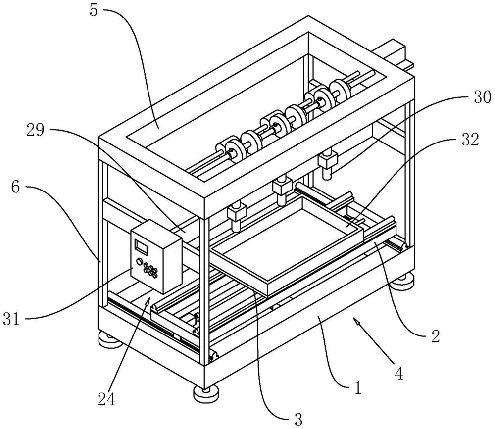
Figure 1 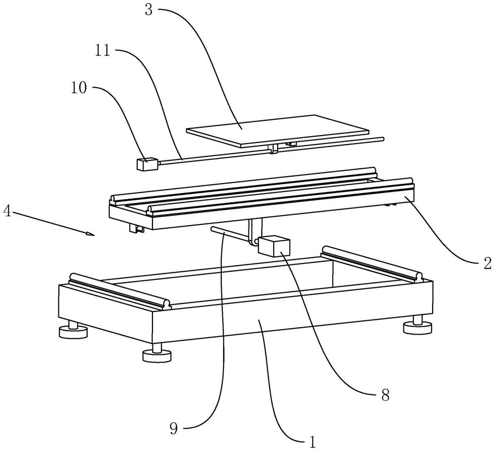
Figure 2 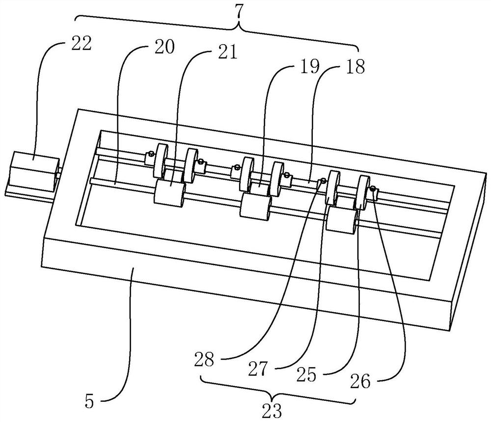
Figure 3
Abstract
Description
technical field
[0001] The present application relates to the technical field of production of ear loop cords, in particular to a winding frame for ear loop cords. Background technique
[0002] It is known that both earmuffs and masks need earloop ropes, which are formed by weaving during the production process. The existing earloop ropes are usually woven with materials such as polyester, nylon, spandex, and core-spun yarn. It is known that the ear loop rope is packed directly after weaving. Before weaving, several yarns are woven into a whole rope through the crochet head, and then the knitted rope is directly dropped into the packing carton, so as to realize the collection of the ear loop rope material.
[0003] In view of the above-mentioned related technologies, the inventor believes that the existing direct dependence on the gravity of the rope makes the rope fall into the packing box, and the rope is easy to form a high pile in the box, which cannot fill the inner ca...
Examples
Embodiment 1
[0031] Embodiment 1, the first aspect The embodiment of the present application discloses a coiling frame for ear loop cords.
[0032] refer to figure 1 , a coil frame for ear loop ropes, comprising a bottom frame 1, the bottom frame 1 is a rectangular frame, the bottom frame 1 is placed on the ground through feet, an installation frame 2 is arranged on the upper surface of the bottom frame 1, the installation frame 2 Slide along the width direction of the bottom frame 1, the upper surface of the installation frame 2 is provided with a placement plate 3, the placement plate 3 slides along the length direction of the bottom frame 1, the sliding direction of the placement plate 3 is the same as that of the installation frame 2 The sliding direction is set vertically, so that the packing carton used to accommodate the ear loop rope is placed on the upper surface of the placing board 3, and both the placing board 3 and the packing carton can slide along the length direction of the...
Embodiment 2
[0040] Embodiment 2, the second aspect The embodiment of the present application discloses a winding frame for earloop cords.
[0041] refer to Figure 4 The difference between the second embodiment and the first embodiment is that the drive assembly 4 includes a third servo motor 12, a third reciprocating lead screw 13 and is arranged on the bottom frame 1 for driving the placement plate 3 along the installation frame 2. The connecting assembly 14 reciprocatingly slides in the length direction, the third servo motor 12 is fixed on the bottom surface of the bottom frame 1, the third reciprocating screw 13 is rotatably connected to the bottom surface of the bottom frame 1, and the third reciprocating screw 13 is coaxially fixed on the bottom surface of the bottom frame 1. On the rotating shaft of the third servo motor 12 , the mounting frame 2 is screwed to the third reciprocating lead screw 13 .
[0042] refer to Figure 4 , the connection assembly 14 includes a rack 15, a g...