
Low-noise pneumatic tire tread pattern
A technology for pneumatic tires and tread patterns, applied to tire treads/tread patterns, tire parts, vehicle parts, etc., can solve the problems of small number of resonators, large size, and no consideration of secondary split peaks of resonators , to achieve the effect of widening the anechoic frequency band, strengthening the attenuation effect, and small feature size
Patent Information
- Authority / Receiving Office
- CN · China
- Current Assignee / Owner
- Publication Date
- 2021-07-23
Smart Images
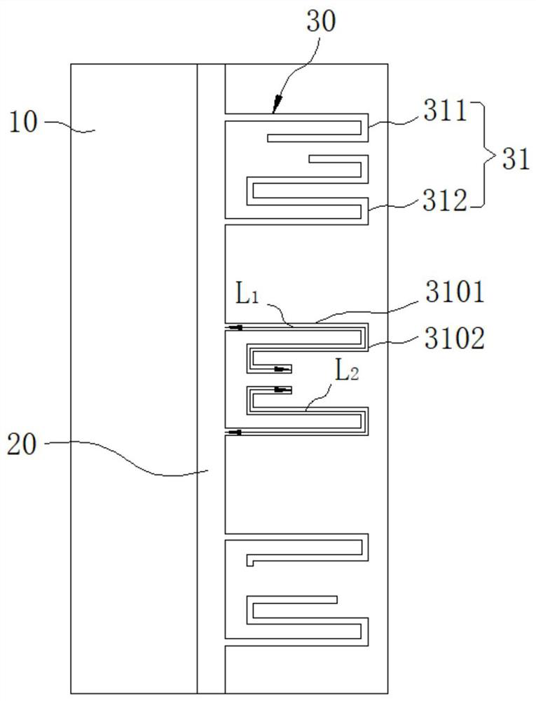
Figure 1 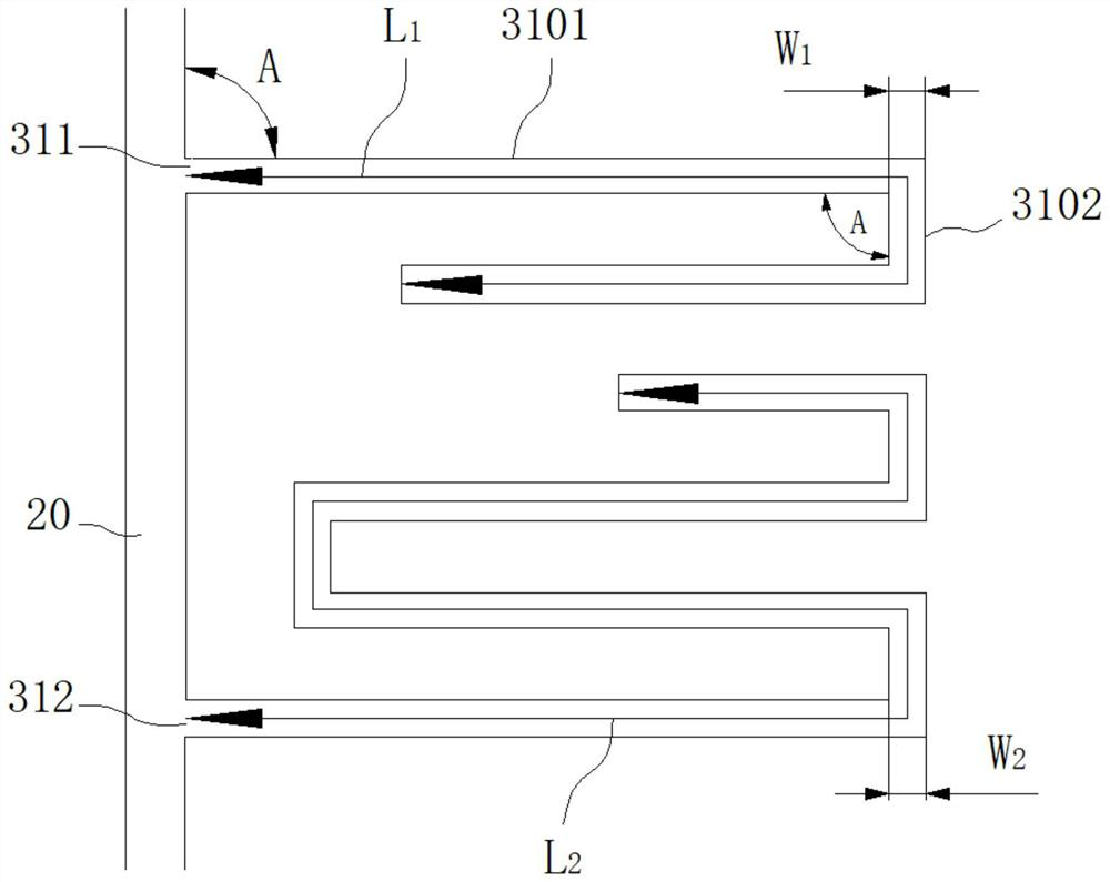
Figure 2 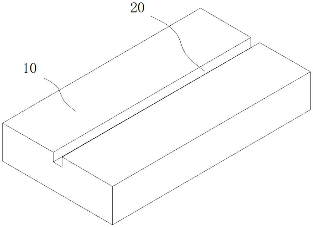
Figure 3
Abstract
Description
technical field
[0001] The invention relates to the technical field of tread pattern of a pneumatic tire, in particular to a tread pattern of a pneumatic tire for reducing resonance noise of a tire tube cavity. Background technique
[0002] As the engine noise and vehicle body vibration noise are well controlled, the proportion of tire noise in vehicle noise has further expanded. As one of the main sources of tire noise, tire cavity resonance noise needs to be well controlled from the perspective of protecting the physical and mental health of drivers. The resonance noise of the tire tube cavity is caused by the air column resonance generated by the pipe with openings at both ends formed by the longitudinal groove of the tire tread and the ground. This noise is generally generated in the range of 800-1200Hz, which is in the frequency band that the human ear is more sensitive to. Therefore, the control of tire tube resonance noise becomes very important.
[0003] In order t...
Examples
Embodiment
[0032] refer to figure 1 , figure 2 , Figure 6 , Figure 7 , a tread pattern of a low-noise pneumatic tire, comprising a longitudinal groove 20 extending circumferentially along a crown 10 and a plurality of resonators 30 spaced apart from each other and connected in parallel on one side of the longitudinal groove 20, each resonator comprising:
[0033] Two adjacent narrow grooves 31, each narrow groove extends along the crown surface away from the longitudinal groove to form a plurality of end-to-end transverse passages 3101 and vertical passages 3102, and the angle between the first extending transverse passage away from the direction of the longitudinal groove is A, in this embodiment A is 90°, and the vertical channels are distributed parallel to the longitudinal grooves, and the adjacent horizontal channels are arranged in parallel;
[0034] Wherein, the number of end-to-end contact points between the transverse channel 3101 and the vertical channel 3102 is at least ...