
Experimental device and method for observing generation of hydrates promoted by microbubbles through nuclear magnetism
An experimental device and technology of micro-bubbles, which are applied in the fields of analysis by nuclear magnetic resonance, measurement devices, material analysis through resonance, etc., can solve the problems of slow formation rate, high formation conditions, and long induction time
Patent Information
- Authority / Receiving Office
- CN · China
- Patent Type
- Applications(China)
- Current Assignee / Owner
- Publication Date
- 2021-09-07
Smart Images
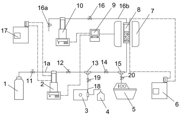
Figure 1 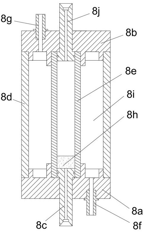
Figure 2 
Figure 3
Abstract
Description
technical field
[0001] The invention belongs to the field of hydrate application, and relates to an experimental device and method for promoting the formation of hydrate by using nuclear magnetic observation of microbubbles. Background technique
[0002] Magnetic resonance imaging (MRI) technology has the advantages of fast, accurate, non-destructive and intuitive observation and display of test samples, and has achieved good application results in the fields of medicine, materials and petrochemistry. In the field of hydrate research, NMR / MRI technology has also attracted more and more researchers' attention because of its strong potential and functions in detecting the internal structure of hydrates / hydrates. Therefore, the SEMS pulse sequence in the high-field MRI system can be used to obtain the two-dimensional MR proton density images of the experimental samples in real time, so as to realize the dynamic monitoring of the in situ generation of microbubbles and hydrate pr...
Examples
Embodiment Construction
[0028] The specific embodiments of the present invention will be described in detail below in conjunction with the technical solutions and accompanying drawings.
[0029] figure 1 and figure 2 Shown is an experimental device for NMR observation of microbubbles to promote the formation of hydrates, which includes a gas cylinder 1 , a solution bottle 4 , a vacuum pump 5 , a data acquisition system 9 and a high-pressure reactor 8 . The high-pressure reaction kettle 8 is placed in the nuclear magnetic signal detection area of the high-field nuclear magnetic instrument 7, and an inner pipe 8e and an outer pipe 8d are arranged between the inlet head 8a and the outlet head 8b of the high-pressure reaction kettle 8, which are fixed on the inlet head 8a The upper end surface of the air intake micro-pipe 8c on the top is in contact with the perforated plate 8h arranged in the inner pipe 8e; a cooling liquid chamber 8i is formed between the inner pipe 8e and the outer pipe 8d, and th...